19
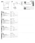
Bolt sizes and torques
~
4C
Nut M1 0
Contact surface
Washer
Conical spring washer
~
4B
4A
Installation of the ISM
in fixed position
Installation of the ISM in
withdrawable position
Fixing points, primary terminals
Required fixing points
(in each case)
1
Bus bars and cables shall be connected with the ISM primary terminals mechanically in a stress-free manner.
No pressure, tension or torsion forces shall act on the ISM. To avoid unacceptably high mechanical loads on the ISM,
the bus bar connections shall rest on additional supporting insulators (Figure 22).
The following limits for maximum unsupported busbar length shall be applied to the design:
ISM15_LD_X
0.5 m
ISM25_LD_X
0.5 m
Other dimensions necessary for correct mounting are indicated in the overall drawings.
Figure 22
Figure 23
Terminals:
M10 stud
Torque 30 3 Nm
Fixing points:
Internal thread M16
Torque 70 7 Nm
Fixing points:
Internal thread M1 0
Torque 30 3 Nm
+_
+_
+_
Terminals:
holes Ø 10.5 mm
Required fixing points
(for withdrawable versions)
Each two fixing points are required,
either 4A+4B or 4A+4C (for fixed
installations)
3
2
3
Содержание ISM_LD Series
Страница 2: ......
Страница 6: ...6 1 Introduction 1...
Страница 11: ...11 2 Receiving Handling and Storage...
Страница 17: ...17 Ins tallation 3...
Страница 34: ...34 4 Switching and Control Functions 4...
Страница 38: ...38 5 Commiss ioning Operation Maintenance 5...
Страница 41: ...41 6 Signalling 6...
Страница 45: ...45 6 Product Line 6...
Страница 47: ...47 7 Dimens ions and Weights 7...
Страница 53: ...53 8 Circuit Diagrams 8...
Страница 54: ...54 ISM_LD with CM_16_1 Control Module 8...
Страница 55: ...55 8 ISM_LD with CM_1501_01 Control Module...
Страница 56: ...56 9 Technical Data 9...
Страница 62: ...62 9 9...
Страница 63: ...63 10 Regulations and Ambient Conditions 10...
Страница 65: ...65 11 Legal Information 11...
Страница 69: ...69 11 Date...


