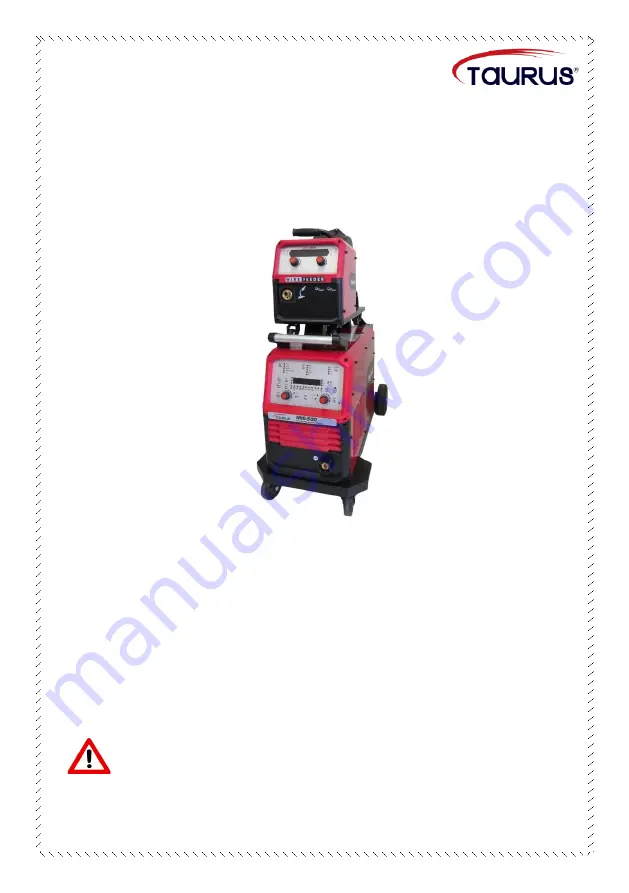
Digital Inverter Pulsed Gas Metal
Arc Welding Machine
MODELS
MIG-350 PLUS & MIG-500 PLUS
Operation Manual
Read this manual carefully before installing,
operating and maintaining the machine.
Страница 1: ...Digital Inverter Pulsed Gas Metal Arc Welding Machine MODELS MIG 350 PLUS MIG 500 PLUS Operation Manual Read this manual carefully before installing operating and maintaining the machine...
Страница 2: ...nted in this operation manual This manual will contain as far as possible preventive and safe operation measures related to the equipment but cannot exclude the occurrence of accidents Therefore the m...
Страница 3: ...3 Warnings 4 Packaging and Transportation 7 Parameters 8 Product Description 8 Working Principle 16 Installation and Wiring 17 Brief instruction for Welding Operation 26 Maintenance 29 Common Machine...
Страница 4: ...the following safety precautions must be followed 1 The operator must be suitably qualified and certificated before operating the equipment 2 A qualified professional should be employed to ensure that...
Страница 5: ...kin damage Avoid clothes with front pockets and button up sleeves and collars 3 Use appropriate flame retardant shields or curtains to protect bystanders from arc radiation and high temperature sparks...
Страница 6: ...well as a secure ground clamp is important 2 Insulation layers of electric wires and cables must be checked regularly for wear and replaced if necessary 3 All equipment used and clothing worn during...
Страница 7: ...achine Protection from Fumes and Gases During the welding or cutting process fumes can be produced which may be detrimental to health 1 The working area should be well ventilated and welding cutting a...
Страница 8: ...n use If there is no hose connected to the flowmeter then cover the outlet with a dust cap Protection Against Moving and Rotating Parts Moving parts such as fans rotors and belts can be hazardous 1 En...
Страница 9: ...0 550 wire feeder Net weight 59kg main body 22kg wire feeder 79kg main body 24kg wire feeder Product Description This semi automatic high performance inverter pulse MIG machine is designed for Argon o...
Страница 10: ...ble welding process are remarkable characteristics 1 4 Negligible splatter and a high metal deposition rate 1 5 Good quality welding seam with very small deformation 1 6 High arc ignition success rate...
Страница 11: ...h 3 Control panel Welding parameter settings and display 4 Wire reel snail shell Welding wire dust prevention 5 Backwater outlet Connects to the backwater outlet on the water cooler 6 Water outlet Con...
Страница 12: ...responding light is lit 5 Memory button Ten sets 0 9 of adjusted welding parameters can be recalled and saved during each operation 6 Save button Save the finished welding parameters 7 Right menu opti...
Страница 13: ...Each function parameter setting value actual parameter value and related information is displayed on the screen Wire feed Display Panel 1 Wire feed speed display The wire feed speed is displayed in m...
Страница 14: ...d speed and material thickness are linked When one of the parameters are adjusted the other two are automatically adjusted to fit the combination The built in highly intelligent technology is so sophi...
Страница 15: ...d Release the trigger and continue the welding operation according to the welding current Press and release the switch to end the operation 4 3 Special 4T Mode Press the torch trigger and the welding...
Страница 16: ...lowing table For welding aluminium plate 1 2mm wire is normally recommended For copper stainless steel and carbon steel 1 0mm or 1 2mm wire is normally recommended Welding method Wire type Diameter mm...
Страница 17: ...Working Diagram No Item No Item 1 Welding piece 8 Gas cylinder valve 2 Earth clamp 9 Gas flowmeter 3 Wire feeder 10 Gas cylinder 4 Inner connecting cable 11 Flowmeter heater power cord 5 Welding mach...
Страница 18: ...excellent welding performance Installation and Wiring 1 Location Requirements 1 1 The machine should not be installed in an area where it is exposed to direct sunlight or rain but where the humidity i...
Страница 19: ...are for reference only 3 Main Power Supply Connection Pay attention to prevent electric shock Wear goggles Warning Take note of the following when the welding machine is connected to the main power s...
Страница 20: ...ive wire L1 4 Overcurrent protection device 2b Live wire L2 5 GND 2c Live wire L3 6 Earth wire terminal block 2d Earth wire 7 Electric control box 4 Gas cylinder Connection Explosion hazard Prevent ga...
Страница 21: ...outlet from dust and dirt 4 4 Mount the flowmeter to the cylinder 4 5 Connect the gas hose firmly from the flowmeter outlet to the gas inlet situated at the back of the welding machine Gas leakage is...
Страница 22: ...le on the spool slide the spool onto the hub shaft and fasten the hub nut as explained below in clause 5 2 Brake Force Tension Adjustment Applying a hexagon socket wrench adjust the screw fastener to...
Страница 23: ...Drive roll 2 Tensioner roller 6 2 Selection of Tensioner Roller and Drive Roll Non groove U groove Non groove Tensioner roller Drive roll V groove U groove knurled V groove roll Suited for hard wires...
Страница 24: ...ing wire as well as wire feeding conditions After adjustment of the drive roll press the tensioner roller Should the wire slip when exiting the contact tip readjust Attention Take care not to apply ex...
Страница 25: ...re liner into the torch leaving approximately 60mm of the liner outside the torch Set up the welding torch into the Euro adapter Wire liner should be left about 5mm outside Take care Ensure the wire l...
Страница 26: ...y part The speed of the wire exiting the nozzle can cause a nasty jab Installation Steps a Open the Tensioner roller b Pull approximately 150mm wire from the spool c Feed the wire through the wire fee...
Страница 27: ...r supply of the machine 1 3 Confirm the gas in the gas cylinder is sufficient no damage to the gas hose and flowmeter 1 4 Confirm that the insulation layers on all the wires and cables of the welding...
Страница 28: ...one 3 Select the suitable spool of wire and mount it over the feeder hub as explained in clause 5 1 4 Check the brake force tension is sufficient as explained in clause 5 2 5 Select the suitable drive...
Страница 29: ...the mode as two step 14 Depending on the position of the welding seam the torch should be tilted at an angle suited to the seam If the joint is formed by two pieces at 90 angle the torch and the workp...
Страница 30: ...ooling of the machine is dependent on a designed air flow pattern it is important to return the side cover plate after the cleaning operation Not paying attention to this detail will result in over he...
Страница 31: ...h Blown fuse Replace fuse 2 Machine switched on auto air switch trips immediately Failure of auto air switch Replace auto air switch IGBT damaged Replace IGBT and drive circuit board Three phase bridg...
Страница 32: ...ing supply Replace the thermistor 7 When the torch trigger is pressed and held wire feed is normal but no gas flow Damaged control circuit board Replace the control circuit board Damaged solenoid valv...
Страница 33: ...ut 1 Impure gas or insufficient gas supply 2 Absorption of air during welding 3 Failed preheater 4 Poor gas shielding owing to strong wind 5 Torch nozzle blocked by spatter 6 Too great a distance betw...
Страница 34: ...ing arc 1 Loose or worn contact tip or too large in diameter for the wire thickness 2 Uneven wire spool rotation excessive wear on the groove of the drive roll and the pressure from the tensioner roll...