m
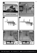
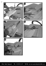
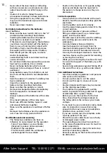
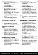
8.4.2 Turn the stop rail (Fig. 23-26)
•
Loosen the wing nuts (f) first in order to turn
the stop rail (e).
•
Now the stop rail can be removed from the
chain bar (h) and replaced with the correct
guide on the guide rail.
•
Re-attach the wing nuts (f).
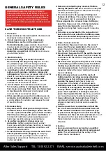
8.4.3 Cutting width (Fig. 26-28)
•
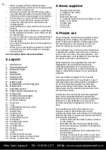
The parallel stop (7) has to be used when
making longitudinal cuts in wooden
workpieces.
•
The parallel stop (7) should be mounted on the
right-hand side of the saw blade (5).
•
Set the parallel stop (7) onto the parallel stop
chain bar (12) (Fig. 26)
•
On the parallel stop chain bar (12) there are
2 scales (j/k) which indicate the distance
between the stop rail (e) and saw blade (5)
(Fig. 27)
•
Choose the correct scale, depending on
whether the parallel stop (e) is turned for
working with thick or thin material.
High parallel stop (thick material): Scale j
Low parallel stop (thin material): Scale k
•
Adjust the parallel stop (7) to the desired
dimension on the gauge (l) and fasten with the
eccentric lever for the parallel stop (28).
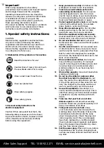
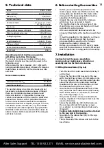
8.4.4 Adjusting the stopping length
(Fig. 29)
•
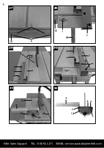
In order to avoid jamming of the workpiece,
the stop rail (e) is longitudinally adjustable.
•
Rule of thumb: The rear end of the stop is
connected to an imaginary line, which begins
approximately at the middle of the saw blade,
and runs towards the rear at an angle of 45°.
•
Set the required cutting width.
•
Slacken the thumb screws (f) and push the
stop rail (e) forward until it touches the
imaginary 45° line.
•
Re-tighten the wing nuts (f)
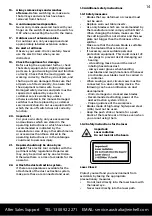
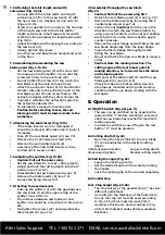
8.5 Adjusting the parallel stop (Fig. 30)
•
Adjust the saw blade to maximum cutting
depth (see also 8.2).
•
Adjust the parallel stop (7) so that the stop rail
(e) touches the saw blade (5) (Setting for thick
material, see also 8.4)
•
If the parallel stop (7) is not lined up with the
saw blade (5), loosen the screws (m) enough
to let the parallel stop align itself parallel to the
saw blade (5) (Fig. 30)
•
Re-tighten the screws (m)
20
After Sales Support TEL: 1300 922 271 EMAIL: [email protected]
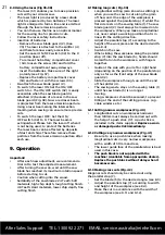
8.6 Cross stop (Fig. 31-32)
•
Insert the cross stop (13) into the groove (29)
of the saw table.
•
Loosen knurled screw (30)
•
Turn the cross stop (13) until the arrow points
to the angle required.
•
Re-tighten the knurled screws (30)
•
When cutting larger workpieces, the cross stop
(13) can be lengthened with the stop rail (e) of
the parallel stop (7) (Fig. 32).
•
In order to lengthen the cross stop (13) with
the stop rail (e), the stop rail (e), the chain
bar (h) and the wing nuts (f) together with
the washer from the parallel stop (7) must be
removed. Now the stop rail is to be attached
as shown in Fig. 32. To do this, use the carriage
bolt (n).
Caution:
•
Do not push the stop rail (e) too far toward the
blade.
•
Distance between the stop rail (e) and saw
blade (5) should be about 2cm.
8.7 Adjusting the scale of the cross stop (Fig. 33)
•
Set an angle of 90° on the saw blade (5).
•
Attach the cross stop (13) to the stop rail (e) of
the parallel stop (7).(See also 8.4).
•
Loosen the knurled screw (30) on the cross
stop (13).
•
Position the cross stop (13) so that the stop rail
is at a 90° angle to the saw blade (5).
•
Now align the cross stop exactly with the
saw blade with the aid of the 90° angle and
re-tighten the knurled screw (30).
•
Check that the cross stop shows exactly 90°. If
this is not the case, proceed as follows:
•
Loosen both screws (o) which are holding the
scale (p) of the cross stop (13) to the cross
stop enough so that this can be adjusted to the
correct position.
•
Now re-tighten the screws (o).
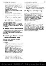
8.8 Adjusting the scale on the saw bench
(Fig. 28; 34)
•
Make sure that the parallel stop (7) runs in line
with the saw blade (5) (see also 8.5)
•
Set the parallel stop so that it touches the saw
blade (5) (Setting for thick material, see also
8.4)
•
Loosen the screw (q) which attaches the scale
(j/k) to the chain bar (12) by about 2 turns.
•
Adjust the scale (j/k) so that the line on the
gauge (l) of the parallel stop (7) is the same as
the zero line on the scale (j).
•
Re-tighten the screw (q).


