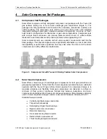


Turbomachinery Package Specification
Taurus
60 Compressor Set and Mechanical Drive
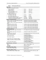
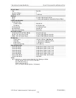
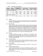
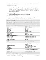
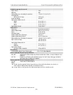
Table 3.
Typical Solar Gas Compressors
Maximum Pressure
Rating
Maximum Flow
Maximum Total Head
Compressor
Family
Number
of Stages
kPa
psig
m
3
/min
ft
3
/min
kJ/kg
ft-lb
f
/lb
m
For Gas Production Applications
C16 1-10
20
700
3000
50
1800
215
72,000
C33 1-12
15
510
2250
270
9500
325
108,000
C40 1-6
17
240
2500
255
9000
255
85,000
C50 1-5
10
350
1500
565
20,000
285
95,000
For Gas Pipeline Applications
C40 1-2
11
040
1600
270
9500
95
32,000
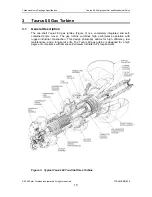
4.2.1 Impellers
Compressor impellers are designed to conservative stress levels. All impellers are
suitable for sour gas applications.
Each impeller, after machining, is proof tested to 115%
of its maximum mechanical speed.
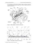
4.2.2 Rotor
Assembly
The rotor assembly consists of stub shafts, impellers, and, if required, rotor spacers (to
maintain a constant bearing span) and a centerbolt. These components are individually
balanced and are rabbet-fit to each other for concentric alignment. Torque is transmitted
through dowel pins. The entire assembly is clamped together with the centerbolt. The
rotor assembly is easy to disassemble. The benefits from this type of construction are
two-fold. Impellers that can be used in a “restaged” rotor are easily salvaged and
downtime is minimized. Reusing old impellers, instead of purchasing new ones to match
new operating conditions, enhances the economic feasibility of restaging to maintain
optimum compressor performance and the lowest possible operating costs.
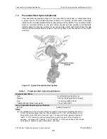
4.2.3 Casings
The pressure-containing outer casing of a compressor is an assembly of three
components: the suction and discharge end caps, which contain the bearing and seal
assemblies, and the centerbody, which holds the rotor and stator assemblies. This is
considered a vertically split “barrel” design. The end caps contain all the service ports for
oil and gas supply and discharge.
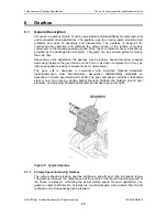
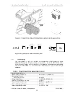
4.2.4 Compressor
Module
The compressor module includes the centrifugal compressor(s) mounted on a structural
steel matching base that, when bolted to the driver skid, forms a continuous base plate
on which all the required subsystems are installed.
4.2.5
Lube Oil System
The gas turbine, gearbox (if required), and compressor modules have a common lube oil
system.
4.2.6
Compressor Dry Seal System
The dry seal system consists of the seal gas and separation gas systems. The seal
system maintains a barrier between the process gas and the compressor bearings. The
separation gas system maintains a barrier between the compressor bearing lube oil and
the dry gas seals.
© 2009 Solar Turbines Incorporated. All rights reserved.
TPS60CSMD/309
15


