background image

26

Содержание T-WAY

Страница 1: ...INSTALLATION GUIDE T WAY D MNL0TWAY 19 10 2020 Rev 00 IT Istruzioni originali ...

Страница 2: ... liability for improper installation or use of the product or for damage deriving from unauthorized modifications to the system Only use genuine spare parts if replacements or repairs are required The manufacturer cannot be held liable for the way the doors or gates to be automated are constructed or for damages caused by failure to build the doors and gates in compliance with good workmanlike tec...

Страница 3: ...4 pag 23 GUARANTEE pag 26 MANUFACTURER S DECLARATION OF INCORPORATION pag 27 1_ CARATTERISTICHE TECNICHE pag 4 2_ IMPIANTO TIPO pag 4 3_ SEZIONE E RIFERIMENTI DELL AUTOMAZIONE pag 4 4_ DIMENSIONE DELLE ANTE E DISPOSIZIONE COMPONENTI pag 6 5_ INSTALLAZIONE pag 16 6_ POSIZIONAMENTO FINECORSA SU T WAY2S T WAY2D T WAY4 pag 17 7_ REGOLAZIONE DELLA TENSIONE DELLA CINGHIA E APERTURA FACILITATA DEL CARTER...

Страница 4: ...230 Vac 10 50 60 Hz Type of work Continuous 100 Operating temperature 15 C 55 C Beam dimensions 120 x 210 mm x length max 3000 mm Degree of protection IP 22 Electric motor 48V DC Ext accessories power supply 12 e 24Vac 1 TECHNICAL FEATURES 2 IMPIANTO TIPO 3 AUTOMATION SECTION AND REFERENCES 1 Infrared sensor 2 Emergency button 3 Keypad for programming 4 Photocell ft transmitting ph Fr receiving ph...

Страница 5: ... 14 Main crosspiece 3 Motor unit with encoder 9 Slow leaf belt support 15 Sliding rail 4 Beam intermediate fixing 10 Double pulley complete transmission 16 Guard 5 Carriage connecting bar 11 Single pulley complete transmission 17 Guard compensator profile 6 Auxiliary carriage connection 12 Anchoring profile 18 Rail seal 1 4 9 11 12 10 4 5 6 7 8 1 2 3 13 14 15 15 16 17 18 18 12 Guard opening empty ...

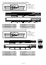
Страница 6: ... length mm B Control central position 70 mm PL Free passage m C Single pulley position 707 mm LA Leaf width mm D Double pulley position 55 mm S Leaves overlapping 23 mm E Electric lock position 35 mm 4 2 TWO LEAF OPENING TO THE LEFT W O ELECTRIC LOCK WITH BATTERY S LT PL G LA LEGEND LT BEAM CUT LENGTH PL FREE PASSAGE LA LEAF WIDTH G FINAL STOP S LEAVES OVERLAPPING 391 A C LT D LA S PL A Motor axle...

Страница 7: ... pulley position 718 mm LA Leaf width mm D Double pulley position 55 mm S Leaves overlapping 23 mm E Electric lock position 35 mm 4 4 TWO LEAF OPENING TO THE LEFT W O ELECTRIC LOCK WITHOUT BATTERY S LT PL G LA LEGEND LT BEAM CUT LENGTH PL FREE PASSAGE LA LEAF WIDTH G FINAL STOP S LEAVES OVERLAPPING D C 391 B A LC LA S PL A Motor axle position 85 mm LT Beam cut length mm B Control central position ...

Страница 8: ...when PL is known Calculation of PL when LT is known LT 3 PL G S 2 PL 2 LT S G 3 LA PL G S 2 Below are some examples of telescopic sliding doors calculated by assuming a leaf overlap S 23mm and a final stop G 0mm each one with its relative installable accessories ...

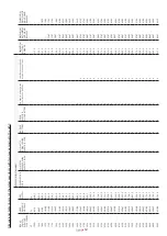
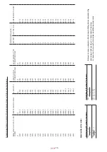
Страница 9: ... 2250 1484 7 765 3 X X X X X X 2262 2297 2285 2350 1551 3 798 7 X X X X X X X 2362 2397 2385 2550 1684 7 865 3 X X X X X X X 2562 2597 2585 2750 1818 0 932 0 X X X X X X X 2762 2797 2785 2950 1951 3 998 7 X X X X X X X 2962 2997 2985 3150 2084 7 1065 3 X X X X X X X 3162 3197 3185 3350 2218 0 1132 0 X X X X X X X 3362 3397 3385 3550 2351 3 1198 7 X X X X X X X 3562 3597 3585 3750 2484 7 1265 3 X X...

Страница 10: ... Single pulley position 720 mm LA Leaf width mm D Double pulley position 55 mm S Leaves overlapping 23 mm E Electric lock position 135 mm 4 6 TWO LEAF OPENING TO THE RIGHT WITH BATTERY S LT PL G LA LEGEND LT BEAM CUT LENGTH PL FREE PASSAGE LA LEAF WIDTH G FINAL STOP S LEAVES OVERLAPPING 391 A C D LT PL S LA A Motor axle position 568 mm LT Beam cut length mm B Control central position 0 mm PL Free ...

Страница 11: ...trol central position 228 mm PL Free passage m C Single pulley position 650 mm LA Leaf width mm D Double pulley position 55 mm S Leaves overlapping 23 mm DIMENSION WITH SIDES Calculation of LT when PL is known Calculation of PL when LT is known LT 3 PL G S 2 PL 2 LT S G 3 LA PL G S 2 Below are some examples of telescopic sliding doors calculated by assuming a leaf overlap S 23mm and a final stop G...

Страница 12: ...85 2600 1718 0 882 0 X X X X X X 2612 2647 2635 2700 1784 7 915 3 X X X X X X X 2712 2747 2735 2750 1818 0 932 0 X X X X X X X 2762 2797 2785 2950 1951 3 998 7 X X X X X X X 2962 2997 2985 3150 2084 7 1065 3 X X X X X X X 3162 3197 3185 3350 2218 0 1132 0 X X X X X X X 3362 3397 3385 3550 2351 3 1198 7 X X X X X X X 3562 3597 3585 3750 2484 7 1265 3 X X X X X X X 3762 3797 3785 3950 2618 0 1332 0 ...

Страница 13: ...gle pulley position 683 mm LA Leaf width mm D Double pulley position 55 mm S Leaves overlapping 23 mm 4 9 4 LEAVES OPENING WITHOUT ELECTRIC LOCK WITH BATTERY LT LA PL S S G LEGEND LT BEAM CUT LENGTH PL FREE PASSAGE LA LEAF WIDTH G FINAL STOP S LEAVES OVERLAPPING F G F G D C A 391 LA S PL LT 76 20 20 A Motor axle position 441 mm LT Beam cut length mm B Control central position 0 mm PL Free passage ...

Страница 14: ...r the use of a connection bar fixed between the left support carriage of the slow moving leaf on the right side of the beam and a special return carriage connected to the traction belt The carriage connection bar must be cut and drilled following the dimensions shown in the figure above and fixed to the carriages using the screws ...

Страница 15: ...6 X 3962 4150 2736 0 707 0 563 549 X 4162 4350 2869 3 740 3 596 582 X 4362 4550 3002 7 773 7 630 616 X 4562 4750 3136 0 807 0 663 649 X 4762 4950 3269 3 840 3 696 682 X 4962 5150 3402 7 873 7 730 716 X 5162 5350 3536 0 907 0 763 749 X 5362 5550 3669 3 940 3 796 782 X 5562 5750 3802 7 973 7 830 816 X 5762 5950 3936 0 1007 0 863 849 X 5962 6150 4069 3 1040 3 896 882 X 6162 6350 4202 7 1073 7 930 916...

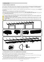
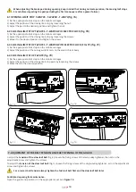
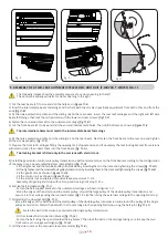
Страница 16: ... beam and the wall be careful not to damage the sliding track C as it would compromise the operation and quietness of the automation Once the beam has been fixed clean the sliding area affected by the drilling residues using a brush or a small vacuum cleaner If there are obstacles to the right or left of the automatic door fit the side caps D before fixing the beam to the wall Fig 1 Fig 2 Fig 3 Fi...

Страница 17: ...t beam on the rear beam and secure it with the end and intermediate screws Fig 6 Then retighten the screws connecting the transmission belts to the carriages fig 2 and finally fit the adjustable brackets of the carriages on the front leaves and then fasten them to the carriages of the front beam fig 5 fig 6 A A B B 6 LIMIT STOP POSITIONING ON T WAY2S T WAY2D T WAY4 The braking pads must be adjuste...

Страница 18: ...RE LA POSIZIONE DEL FINECORSA DI CHIUSURA ALLENTANDO LE VITI E SPOSTARLO NELLA POSIZIONE DESIDERATA E SERRARE LE VITI FINECORSA DI APERTURA T WAY2S T WAY2D T WAY4 REGOLARE LA POSIZIONE DEL FINECORSA DI CHIUSURA ALLENTANDO IL DADO REGOLARE IL TAMPONE NELLA POSIZIONE DESIDERATA E SERRARE IL DADO fig 7C 1 2 3 4 B C D E F FINECORSA DI CHIUSURA T WAY2S T WAY2D CON ELETTROBLOCCO REGOLARE LA POSIZIONE DE...

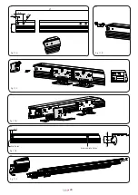
Страница 19: ... insert them into the front beam fig 11 G The locking bracket is fitted only in the versions with electric lock 8 Install the gearmotor control unit pulley transmissions belts and accessories on the front beam according to the configuration of the t way door see assembly diagrams paragraph 4 fig 11 H Fit the tightener and the two belt pulley transmission by inserting them in the track and tighteni...

Страница 20: ...20 15 5 50 56 8 5 LT 15 5 fig 11 A 23 5 32 5 56 0 9 fig 11 B 56 56 15 5 fig 11 C fig 11 F 0 9 15 5 50 56 8 5 LT 23 5 32 5 56 15 5 0 9 fig 11 D fig 11 E End holes Intermediate holes ...

Страница 21: ...21 fig 11 H 1 fig 11 H 2 fig 11 H fig 11 G fig 11 H 3 fig 11 H 5 fig 11 H fig 11 H 6 fig 11 H 4 Version without electric lock Version with electric lock ...

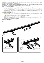
Страница 22: ...inserting the intermediate and lateral fastenings insert 5 carriages four of which are for the rear leaves and one is an auxiliary pulley transmission carriage for the movement of the door opening to the right fig 12 A 2 Fasten the connection bracket to the outermost carriage of the left rear leaf fig 12 B 3 Cut and drill the connection bar to size and fix it between the auxiliary carriage and the...

Страница 23: ...e toothed bracket Then arrange the carriages of both leaves so that the internal carriages are in the closed leaf position Finally connect the belt to the internal carriage of the front right leaf using the toothed bracket fig 12 F 2 7 Installing the slow leaf belt fig 12 G Bring the carriages to the open leaf position wrap the edges of the belt around the small pulley of the double pulley transmi...

Страница 24: ...24 fig 12 F 1 fig 12 F fig 12 F 2 fig 12 D fig 12 E fig 12 G 1 fig 12 G fig 12 G 2 fig 12 G 3 ...

Страница 25: ...following cases If the fault was caused by an installation that was not performed according to the instructions provided by the company inside the product pack If original TAU spare parts were not used to install the product If the damage was caused by an Act of God tampering overvoltage incorrect power supply improper repairs incorrect installation or other reasons that do not depend on TAU If a ...

Страница 26: ...26 ...

Страница 27: ...27 ...

Страница 28: ...28 Via Enrico Fermi 43 36066 Sandrigo VI Italy Tel 39 0444 750190 Fax 39 0444 750376 info tauitalia com www tauitalia com ...

Отзывы: