19
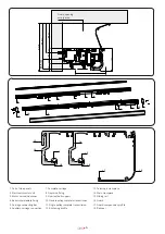
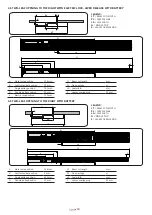
TENSIONAMENTO CINGHIE
N.B. PER UN CORRETTO TENSIONAMENTO CINGHIE TENSIONARE SEMPRE
PRIMA LA CINGHIA VELOCE E POI LA CINGHIA LENTA
PER TENSIONARE LA CINGHIA ANTA VELOCE ALLENTARE LE VITI DI
FISSAGGIO DEL TENDITORE A DUE PULEGGE, AGIRE SULLA VITE DI
REGOLAZIONE E SERRARE LE VITI
PER TENSIONARE LA CINGHIA ANTA LENTA ALLENTARE LE VITI DI
FISSAGGIO DEL TENDITORE A PULEGGIA SINGOLA, AGIRE SULLA
VITE DI REGOLAZIONE E SERRARE LE VITI
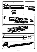
fig. 8
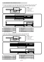
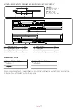
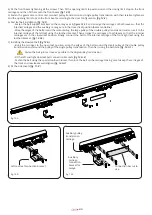
TENSIONAMENTO CINGHIE
N.B. PER UN CORRETTO TENSIONAMENTO CINGHIE TENSIONARE SEMPRE
PRIMA LA CINGHIA VELOCE E POI LA CINGHIA LENTA
PER TENSIONARE LA CINGHIA ANTA VELOCE ALLENTARE LE VITI DI
FISSAGGIO DEL TENDITORE A DUE PULEGGE, AGIRE SULLA VITE DI
REGOLAZIONE E SERRARE LE VITI
PER TENSIONARE LA CINGHIA ANTA LENTA ALLENTARE LE VITI DI
FISSAGGIO DEL TENDITORE A PULEGGIA SINGOLA, AGIRE SULLA
VITE DI REGOLAZIONE E SERRARE LE VITI
fig. 9
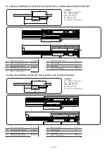
fig. 10
8. ASSEMBLY OF A TWO-LEAF AUTOMATIC TELESCOPIC DOOR KIT (T-WAY2D, T-WAY2S) FIG. 11
The following images show the assembly sequence for a door opening to the left.
The principle is equally valid also for doors opening to the right
1) Cut the rear beam (LT) to size and drill the holes as in
figure 11-A.
2) Insert the intermediate beam fastenings and fix them with the screws in positions equidistant from each other and from the
ends
(fig.11-B)
3) Fit the noise protection profile and the sliding rail on the rear beam. Insert the rear leaf carriages and the right and left side
beam fastenings, then lock them in position with the lower and rear screws.
(fig.11-C)
4) Fasten the connection bracket to the outermost carriage
(fig. 11-D)
5) Cut the front beam (LT) to size and drill the end and intermediate holes. Then drill the flares as shown in
figure 11-E
The intermediate holes must match the intermediate beam fastenings
6) Fit the noise protection profile and the sliding rail on the rear beam. Next fasten the front beam to the rear one and tighten
all the screws properly.
(fig. 11-F)
7) Prepare the front leaf carriages fitting the opening limit stop extension and if necessary the leaf locking bracket (for versions
with electric lock), then insert them into the front beam.
(fig. 11-G)
The locking bracket is fitted only in the versions with electric lock
8) Install the gearmotor, control unit, pulley transmissions, belts and accessories on the front beam according to the configuration
of the t-way door, see assembly diagrams (paragraph 4)
(fig. 11-H)
- Fit the tightener and the two-belt pulley transmission by inserting them in the track and tightening the screws
(fig. 11-H.1)
- Fit the tightener and the slow leaf belt pulley transmission by inserting them in the track and tightening the screws
(fig. 11-H.2)
- Fit the gearmotor as shown in
figure 11-H.3
- Fit the control unit as shown in
figure 11-H.4
- Fit the electric lock and related manual release accessories 11-H.5
Assembly of opening limit stop with rail stop and closing limit stop 11-H.6
9) Fast leaf belt installation
(fig. 11-i)
- Fasten the belt support bracket to the outermost carriage as shown in figure 11-i.1
- Wrap the edges of the belt around the motor pulley, around the large pulley of the double pulley transmission and
secure it to the carriage using the toothed bracket
(fig. 11- i.2).
Then bring the external carriage to the opening limit stop.
110) Installing the slow leaf belt
(fig. 11-J)
-Wrap the edges of the belt around the small pulley of the double pulley transmission and around the pulley of the single
pulley transmission. Fasten the belt with the front carriage to the opening limit stop using the belt joint.
(fig. 11-J.1)
Fasten the belt joint as close as possible to the single pulley transmission
- Fit the slow leaf belt connection bracket
(fig, 11-J.2)
- Fasten the belt using the special toothed fixing bracket. Then lock the belt on the carriage taking care to keep the two
front and rear carriages well aligned
(fig. 11-J.3)
11) Fit the side covers or the manual release accessories
(fig. 11-K)
Содержание T-WAY
Страница 1: ...INSTALLATION GUIDE T WAY D MNL0TWAY 19 10 2020 Rev 00 IT Istruzioni originali ...
Страница 24: ...24 fig 12 F 1 fig 12 F fig 12 F 2 fig 12 D fig 12 E fig 12 G 1 fig 12 G fig 12 G 2 fig 12 G 3 ...
Страница 26: ...26 ...
Страница 27: ...27 ...

