9.Electronic Circuit Description
9.1 Main Board Circuit
(1) Power
Refer to circuit diagram sheet 7 of PWB-0452-03.
The DC +12V output of AC adaptor is applied to the LCD-TV through P020.
This supply is fed directly to P017#1
、
2 (Connector to Inverter). It also provide
+9V for I009 (Audio Pre-Amp PT2314) and IT03 (MTS Decoder : TDA9850)
through two regulators ( RC1117) I011 and I014 respectively.
12V is regulated by I014 (switching regulator : LM2576) to p5V
for the whole system. I014 LM2576 is a step-down regulator ( buckconverter ) and
capable of driving a 30A load. The output voltage of I014#2 could be fixed in 5.0V
±
4% tolerance via R106
、
R107 and R108. In the event of an short or a overload of
external circuit, the internal oscillator frequency will reduce from 52KHz to
approximately 18KHz. This self-protection lowers the average dissipation of the IC
by lowering the duty cycle from 5% ~ 2%, featury 80
μ
A(typical) standby current.
Moreover, if the DC 12V supply drops to less than +7V the +5V O/P will turn to
low . The output of I014#2 5V to Panel via I025 ( Mosfet: MI9933).
It’s also fed into I015 (RC1117) to offer +2.5V supply and into I016 (RC1117) to
offer +3.3V supply to other chips.
(2) PC Signal
Refer to circuit diagram sheet 1 of PWB-0452-03.
The analog R.G B video input signals are supplied through the 15 Pin D-sub cable
which is terminated at PJ03. These three input signals are approximately 0.7Vpp
in amplitude.
R031, R032, and R033 give resistance of 75
Ω
respectively for impedance
matching. These R, G, B video signals are ac coupled via 0.047U capacitor C021,
C016 and C013, and then fed into the I001 AD converter (AD6883-140) at Pin54,
49 and 43 respectively. These analog R,G,B video signals are converted to the their
digital forms in I001. The outputs of digital data including 8 bits red, 8 bits green,
8 bits blue signals are assigned at Pin70~77, Pin2~9, and Pin12~19 of I001, and
applied to Port A of I019 ( Scaler : TP6760) Hsync & Vsync are applied to I001
( AD9883-140)#30 & #31 and the processed signal taken from #66 & #64 are fed
into I019(TP6760) #18, #19.
CLK signal is taken from I001 (AD9883-140) #67 and applied to I019(TP6760)
#156.
The LCD-TV is designed to have the DDC/2B functions. Communication between
the LCD-TV and computer for DDC is via PJ03 (D-sub connector )#15, #12
which are defined as SCL,SDA signals. The computer will read out the EDID from
Содержание V17AFTW
Страница 1: ...V V1 17 7A AF FT TW W LCD TV...
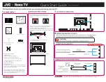
Страница 7: ...3 Connection Applications...
Страница 45: ...P N 5030150001...
Страница 46: ...13 Mechanical Disassembly...
Страница 47: ...7 Block Diagram...
Страница 66: ......
Страница 67: ...CAM350 V 5 0 Wed Nov 6 18 36 34 2002 Untitled...
Страница 68: ...CAM350 V 5 0 Wed Nov 6 18 33 29 2002 Untitled...
Страница 69: ...CAM350 V 5 0 Wed Nov 6 18 41 35 2002 Untitled...
Страница 70: ...CAM350 V 5 0 Wed Nov 6 18 43 02 2002 Untitled...
Страница 71: ...CAM350 V 5 0 Wed Nov 6 18 39 10 2002 Untitled...
Страница 72: ......