background image

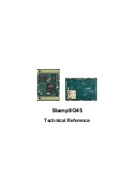
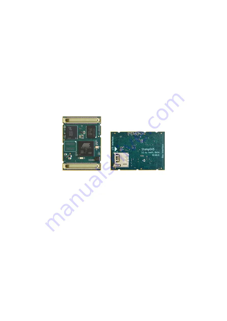
Stamp9G45

Technical Reference

Содержание Stamp9G45

Страница 1: ...Stamp9G45 Technical Reference ...

Страница 2: ...ut errors cannot be excluded Neither the company named above nor the seller assumes legal liability for mistakes resulting operational errors or the consequences thereof Trademarks company names and product names may be protected by law This document may not be reproduced edited copied or distributed in part or in whole without written permission This document was generated on 2014 07 09T15 28 29 ...

Страница 3: ...O 8 4 10 Clock Generation 9 4 10 1 Processor Clocks 9 4 10 2 Programmable Clocks 10 4 11 Power Management Controller PMC 10 4 11 1 Function 10 4 11 2 Power Management 11 4 12 Real time Timer RTT 11 4 13 Timer Counter TC 12 4 14 Periodic Interval Timer PIT 12 4 15 Watchdog Timer 12 4 16 Real time Clock RTC 12 4 17 True Random Number Generator TRNG 12 4 18 Peripheral DMA Controller PDC 13 4 19 Debug...

Страница 4: ...nsiderations 21 5 1 Ethernet Controller EMAC 21 5 2 USB 21 5 2 1 USB Host Controller UHP 21 5 2 2 USB Device Controller UDP 22 5 3 Memory Bus 22 A Peripheral Color Codes 25 B Peripheral Identifiers 26 C Address Map Physical Address Space 27 D Stamp9G45 Pin Assignment 29 E Stamp9G45 Electrical Characteristics 32 F Stamp9G45 Clock Characteristics 33 G Stamp9G45 Environmental Ratings 34 H Stamp9G45 D...

Страница 5: ...res 5 1 Buffered Memory Bus PIOC 1 8V 3 3V 24 H 1 Stamp9G45 Dimensions 35 I 1 Starterkit FX8 36 I 2 Starterkit Buffer 37 I 3 Starterkit Memory 38 I 4 Starterkit Serial 39 I 5 Starterkit Ethernet 40 I 6 Starterkit USB Power 41 ...

Страница 6: ...4 AC97 I O Lines 18 4 5 LCDC palette entry 19 4 6 LCDC 24 bit memory organization 19 B 1 Peripheral Identifiers 26 C 1 Physical Address Space 27 D 1 Pin Assignment BUS Interface 29 D 2 Pin Assignment IO Interface 30 E 1 Electrical Characteristics 32 F 1 Clock Characteristics 33 G 1 Environmental Ratings 34 ...

Страница 7: ...rt a huge variety of peripheral devices Equipped with a 16 Bit parallel bus it gives fast access to a number of chips and additional devices The ARM architecture as a modern and widely supported processor architecture is currently the platform of choice for medium performance embedded devices Almost all major processor manufacturers have ARM products in their portfolio The availability of the wide...

Страница 8: ...x is described in a further document The manual comprises only a brief description of the AT91SAM9G45 processor as this is already described in depth in the manual of the manufacturer Atmel Descriptions of the ARM core ARM926EJ S are available from Atmel and also at http www arm com It is much recommended to have a look at these documents for a thorough understanding of the processor and its integ...

Страница 9: ...y 128 MB NAND flash memory optional up to 1GB 128 MB LPDDR SDRAM optional up to 512 MB 64 KB SRAM 128 Bytes EEPROM Onboard Micro SD Card Slot 3 3 Interfaces and external signals 2x 100 pin fine pitch low profile Connectors Hirose FX8 Ethernet 10 100 Mbit MAC USB 2 0 High Speed Host USB 2 0 Full Speed OTG USB On the Go USB 2 0 High Speed Device Four USARTs One UART One Synchronous Serial Controller...

Страница 10: ...CPU Bus Some of the various functions are realized by multiplexing connector pins therefore not all functions may be used at the same time see Appendix D Stamp9G45 Pin Assignment 3 4 Miscellaneous Three 16 Bit Timer Counter True Random Number Generator Real Time Timer RTT with battery backup support RTC Periodic Interval Timer PIT Watchdog Timer WDT Unique Hardware Serial Number 3 5 Power Supply 3...

Страница 11: ... ARM v4 and v5 Memory Management Unit MMU ARM v5 32 bit Instruction Set ARM Thumb 16 bit Instruction Set supported DSP Instruction Extensions ARM Jazelle Technology for Java Acceleration EmbeddedICE Debug Communication Channel Support Some of these features like Jazelle are currently not supported by the operating system of the product 4 3 Memory The Stamp9G45 is equipped with two 32 Bit external ...

Страница 12: ...evelling filesystems 4 3 2 LPDDR SDRAM The Stamp9G45 is equipped with 128MB LPDDR SDRAM Low power DDR SDRAM Customer specific adaptations allow configurations up to 512MB In 128MB and 256MB configurations the LPDDR SDRAM is connected to EBI0 The external Bus is not affected In 512MB configuration 256MB of the LPDDR SDRAM are connected to chip select one NCS1 of the micrcontroller s EBI1 DDR SDRAM ...

Страница 13: ...6 Data Master 2 PDC Master 3 USB HOST OHCI Master 4 DMA Master 5 DMA Master 6 ISI Controller DMA Master 7 LCD DMA Master 8 Ethernet MAC DMA Master 9 USB Device High Speed DMA Master 10 USB Host High Speed EHCI DMA Master 11 Reserved Table 4 1 Bus Matrix Masters Slave 0 Internal SRAM Internal ROM USB OHCI USB EHCI UDP High Speed RAM LCD User Interface Slave 1 Reserved Slave 2 DDR Port 0 Slave 3 DDR...

Страница 14: ...neral Purpose Backup Registers It is recommended to always use a backup power supply normally a battery in order to speed up the boot up time and to avoid reset problems 4 7 Reset Controller RSTC The embedded microcontroller has an integrated Reset Controller which samples the backup and the core voltage The presence of a backup voltage VDDBU when the card is powered down speeds up the boot time o...

Страница 15: ...ollers are considered as user peripherals This means that the PIO Controller interrupt lines are connected among the interrupt sources 2 to 31 Refer to the PIO Controller peripheral identifier Table B 1 Peripheral Identifiers to identify the interrupt sources dedicated to the PIO Controllers The PIO Controller interrupt can be generated only if the PIO Controller clock is enabled A number of the P...

Страница 16: ... programmable clocks can be individually programmed to derive their input from SLCK PLLA PLLB and Main Clock Each PCK has a divider of 2 4 8 16 32 or 64 The Stamp9G45 features two programmable clocks PCK0 PCK1 4 11 Power Management Controller PMC 4 11 1 Function The PMC has a Peripheral Clock register which allows to individually enable or disable the clocks of all integrated peripherals by using ...

Страница 17: ... a user action or some other rare event In such a case it is possible to change MCK to SLCK Any external event which changes the state on peripheral pins not the USB can then be detected by the PIO controller or the AIC It should also be taken into account that when a PLL is stopped it will take some time to restart it Changing the PLL frequencies or stopping them can therefore be done only at a m...

Страница 18: ...ting system s scheduler interrupt 4 15 Watchdog Timer The watchdog timer is a 12 bit timer running at 256 Hz Slow Clock 128 The maximum watchdog timeout period is therefore equal to 16 seconds If enabled the watchdog timer asserts a hardware reset at the end of the timeout period The application program must always reset the watchdog timer before the timeout is reached If an application program ha...

Страница 19: ... data transfer which improves microcontroller performance To launch a transfer the peripheral triggers its associated PDC channels by using transmit and receive signals When the programmed data is transferred an end of transfer interrupt is generated by the peripheral itself There are four kinds of interrupts generated by the PDC End of Receive Buffer End of Transmit Buffer Receive Buffer Full Tra...

Страница 20: ... a limited processor overhead The MCI supports stream block and multi block data read and write and is compatible with the Peripheral DMA Controller PDC channels minimizing processor intervention for large buffer transfers The MCI operates at a rate of up to Master Clock divided by 2 and supports the interfacing of 2 slot s Each slot may be used to interface with a MultiMediaCard bus up to 30 Card...

Страница 21: ...can also be implemented to power on the board One I O line may be used by the application to check that VBUS is still available from the host Self powered devices may use this entry to be notified that the host has been powered off In this case the pullup on DP must be disabled in order to prevent feeding current to the host The application should disconnect the transceiver then remove the pullup ...

Страница 22: ... hardware handshaking feature enables an out of band flow control by automatic management of the pins RTS and CTS The receive DMA channel must be active for this mode The RTS signal is driven high if the receiver is disabled or if the DMA indicates a buffer full condition As the RTS signal is connected to the CTS line of the connected device its transmitter is thus prevented from sending any more ...

Страница 23: ... master which controls the data flow while the other devices act as slaves which have data shifted into and out by the master A slave device is selected when the master asserts its NSS signal If multiple slave devices exist the master generates a separate slave select signal for each slave NPCS The SPI system consists of two data lines and two control lines Master Out Slave In MOSI This data line ...

Страница 24: ...ve for synchronization is supported for sensors that embed SAV start of active video and EAV end of active video delimiters in the data stream The Image Sensor Interface interrupt line is generally connected to the Advanced Interrupt Controller and can trigger an interrupt at the beginning of each frame and at the end of a DMA frame transfer If the SAV EAV synchronization is used an interrupt can ...

Страница 25: ...31 2 LCDC Frame Buffer The LCDC Frame Buffer typically resides in the external RAM The LCDC video memory is organized as a frame buffer in a straight forward way It supports color depths of 1 2 4 8 16 or 24 bit per pixel The video data is stored in a packed form with no unused bits in the video memory The color resolutions of 1 2 4 and 8 bpp bits per pixel use a palette table which is made up of 1...

Страница 26: ...he Stamp9G45 has additional to touch panel support three ADC channels available The Touch Screen ADC Controller is a 10 bit Analog to Digital Converter supporting resistive touch screen panels It can be used as Touch Screen Controller ADC or both supporting eight lines maximum It integrates a 8 to 1 analog multiplexer for analog to digital conversions of up to 8 analog lines four power switches th...

Страница 27: ...ended for applications which are subject to external contact The restrictions with regard to capacitive loading have to be applied when selecting a protection device A circuit to generate the 5V VBUS supply voltage VBUS considerations for USB Host A USB host port has to provide a supply voltage VBUS of 5V 5 which has to be able to source a maximum of 500mA or 100mA in case of battery operation Ple...

Страница 28: ...red to be switchable in order not to source current to an attached but powered down host This would otherwise constitute an irregular condition on the host The software has to take care of this fact The capacitors are intended to improve the signal quality edge rate control depending on the specific design They are not mandatory The total capacitance to ground of each USB pin the PCB trace to the ...

Страница 29: ...pin of the module is powered by the module itself Do not power this pin externally to maintain inter product dependencies A difference between Vmem and VCC may also affect the behaviour of one PIO controller of the respective module To connect 3 3V chips to the memory bus or to maintain compatibility between various products it is recommended to implement buffer chips on the memory bus externally ...

Страница 30: ...Design Considerations 24 Figure 5 1 Buffered Memory Bus PIOC 1 8V 3 3V ...

Страница 31: ... Device Reserved Synhcronous Serial Controller SSC JTAG Control Ethernet Genral Purpose I O Port Programmable Clock Output Analog to digital Converter Timer Counter Image Sensor Interface LCD TFT Controller Interface Embedded Trace Macrocell Static Memory Controller Compact Flash Interface Pulse Width Modulator Touch Controller Can Controller AC97 Sound Interface Encryption Device Soft Modem True ...

Страница 32: ...ace 0 12 TWI0 Two Wire Interface 0 13 TWI1 Two Wire Interface 1 14 SPI0 Serial Peripheral Interface 15 SPI1 Serial Peripheral Interface 16 SSC0 Synchronous Serial Controller 0 17 SSC1 Synchronous Serial Controller 1 18 TC0 TC5 Timer Counter 0 1 2 3 4 5 19 PWM Pulse Width Modulation Controller 20 TSADCC Touch Screen ADC Controller 21 DMA DMA Controller 22 UHPHS USB Host High Speed 23 LCDC LCD Contr...

Страница 33: ...0 0000 UDPHS USB Device Port DMA 70 0000 USB OHCI USB OHCI controller 80 0000 USB EHCI USB EHCI controller 1000 0000 EBI_1 NCS0 Chip Select 0 2000 0000 EBI_1 NCS1 Chip Select 1 DDRAM 3000 0000 EBI_1 NCS2 Chip Select 2 4000 0000 EBI_1 NCS3 Chip Select 3 NAND 5000 0000 EBI_1 NCS4 Chip Select 4 CF_1 6000 0000 EBI_1 NCS5 Chip Select 5 CF_2 7000 0000 EBI_0 NCS0 Chip Select 0 DDRAM FFF7 8000 UDPHS USB D...

Страница 34: ...atrix User Interface FFFF EE00 DBGU Debug Unit including UART FFFF F000 AIC Advanced Interrupt Controller FFFF F200 PIOA 32 Bit Parallel I O Controller A FFFF F400 PIOB 32 Bit Parallel I O Controller B FFFF F600 PIOC 32 Bit Parallel I O Controller C FFFF F800 PIOD 32 Bit Parallel I O Controller D FFFF FA00 PIOE 32 Bit Parallel I O Controller E FFFF FC00 PMC Power Management Controller FFFF FD00 RS...

Страница 35: ...0 EBI1 A21 NANDCLE PC4 24 25 PC5 EBI1 A22 NANDALE EBI1 A23 PC6 26 27 PC7 EBI1 A24 EBI1 A25 CFRNW PC12 28 29 GND GND 30 31 PD8 AC97FS TIOB5 TCLK5 AC97CK PD9 32 33 PD7 AC97TX TIOA5 AC97RX PD6 34 35 EBI1 NCS0 EBI1 NCS1 SDCS 36 37 PC13 EBI1 NCS2 EBI1 NCS3 NANDCS PC14 38 39 PC10 EBI1 NCS4 CFCS0 TCLK2 CTS2 EBI1 NCS5 CFCS1 PC11 40 41 PC0 DQM2 DQM3 PC1 42 43 EBI1 NRD CFOE EBI1 NWR0 NWE CFWE 44 45 EBI1 NWR...

Страница 36: ...MS 96 97 TDO TCK 98 99 GND GND 100 Table D 1 Pin Assignment BUS Interface Pin GPIO Periph A Periph B Add Function Add Function Periph B Periph A GPIO Pin 1 VCC VCC 2 3 PA17 ETXCK ERXDV PA15 4 5 PD22 TIOA2 TSAD2 TSAD3 TCLK0 PD23 6 7 BMS TSADVREF 8 9 PE3 LCD VSYNC LCD HSYNC PE4 10 11 PE5 LCD DOTCK LCDDEN PE6 12 13 PE2 LCDCC LCDD2 LCDD0 PE7 14 15 PE8 LCDD1 LCDD3 LCDD4 LCDD2 PE9 16 17 PE10 LCDD3 LCDD5...

Страница 37: ...5 56 57 PA6 MCI0 DA4 ETX2 ETX3 MCI0 DA5 PA7 58 59 PA8 MCI0 DA6 ERX2 ERX3 MCI0 DA7 PA9 60 61 PB4 TXD1 RXD1 PB5 62 63 PD16 RTS1 CTS1 PD17 64 65 PB6 TXD2 RXD2 PB7 66 67 PD20 TIOA0 TSAD0 TSAD1 TIOA1 PD21 68 69 PB13 DTXD DRXD PB12 70 71 PD29 TCLK1 SCK1 GPAD6 PWM2 PCK0 PD26 72 73 PD14 TF1 RF1 PD15 74 75 PD12 TK1 PCK0 RK1 PD13 76 77 PD10 TD1 RD1 PD11 78 79 PA1 MCI0 CDA TIOA3 TCLK3 MCI0 CK PA0 80 81 PA2 M...

Страница 38: ... V VRES Reset Treshhold 2 9 V TRES Duration of Reset Pulse 150 280 ms 3 3V 2 0 VCC 0 3 V VIH High Level Input Voltage PIOC4 PIOC31 1 8V 1 26 2 1 V 3 3V 0 3 0 8 V VIL Low Level Input Voltage PIOC4 PIOC31 1 8V 0 3 0 54 V Normal Operation 345 mW Full Load max 457 mW Stand By 266 mW P Power Down 125 mW VBATT Battery Voltage 2 0 3 0 VCC V Ambient temp 25 5 µA Ambient temp 70 17 µA IBATT Battery Current...

Страница 39: ...e Unit MAINCK Main Oscillator frequency 12 000 MHz SLCK Slow Clock 32 768 KHz PLLACK PLLA Clock MAINCK 800 000 MHz PCK Processor Clock PLLACK 400 000 MHz MCK Master Clock PCK 133 000 MHz DDCK DDRAM Clock MCK 266 000 MHz BCK Baudrate Clock MCK 1 5 8 25 max MHz UPLLCK USB Clock MAINCK 0 25 480 000 MHz Table F 1 Clock Characteristics ...

Страница 40: ...onmental Ratings Operating Storage Symbol Description Parameter Min Max Min Max Unit TA Ambient temperature 30 85 45 85 Relative Humidity no condensation 90 90 RH Absolute Humidity Humidity TA 60 90 RH Corrosive Gas not admissible Table G 1 Environmental Ratings ...

Страница 41: ...Stamp9G45 Dimensions 35 Appendix H Stamp9G45 Dimensions Figure H 1 Stamp9G45 Dimensions ...

Страница 42: ...D14 EBI1_D15 EBI1_ADDRESS EBI1_NBS0 A0 EBI1_NBS2 NWR2 A1 EBI1_A02 EBI1_A03 EBI1_A04 EBI1_A05 EBI1_A06 EBI1_A07 EBI1_A08 EBI1_A09 EBI1_A10 EBI1_A11 EBI1_A12 EBI1_A13 EBI1_A14 EBI1_A15 EBI1_BA0 A16 EBI1_BA1 A17 EBI1_A18 PC2 A19 PC3 A20 PC4 A21 NANDALE PC5 A22 NANDCLE PC6 A23 PC7 A24 PC12 A25 CFRNW PD8 AC97FS TIOB5 PD9 AC97CK TCLK5 PD7 AC97TX TIOA5 PD6 AC97RX EBI1_NCS0 PC13 NCS2 PC10 NCS4 CFCS0 TCLK2...

Страница 43: ...9 D 74ALVC00 10 9 8 IC9 C 74ALVC00 14 7 IC9 E 74ALVC00 R9 1k J5 J12 C6 100nF C7 100nF C8 100nF C10 100nF C11 100nF C12 100nF C13 100nF C14 100nF C15 100nF C16 100nF C17 100nF C18 100nF C19 100nF C20 100nF C21 100nF J26 J27 J28 J29 EBI1_D 00 15 EBI1_D00 EBI1_D02 EBI1_D04 EBI1_D06 EBI1_D08 EBI1_D10 EBI1_D12 EBI1_D14 EBI1_D15 EBI1_D13 EBI1_D11 EBI1_D09 EBI1_D07 EBI1_D05 EBI1_D03 EBI1_D01 BEBI1_D 00 1...

Страница 44: ...DO 4 VTREF 5 TMS 6 SRST 7 VSUP 8 TRST 9 TDI 10 GND X12 Wanne 10 pol C104 100nF SP1 PS1240P02CT3 TDK e 13 12 11 IC18 D 74LVC86 R24 330r e 9 10 8 IC18 C 74LVC86 R25 330r 14 VCC 7 GND IC18 E 74LVC86 C80 100nF 1 2 J10 8 SO 1 SI 2 SCK 4 CS 3 RES 6 VCC 7 GND 5 WP IC11 AT45UNI J11 R10 100r J14 C9 100nF J18 J19 R13 10k e 4 5 6 IC18 B 74LVC86 J8 J7 1 2 J48 J49 R17 100k SW2 DTSM61N PA3 MCI0_DA1 TCKL4 PA2 MC...

Страница 45: ...R5IN 28 C1 24 C1 1 C2 2 C2 IC15 A MAX3243 C75 100n 16V X7R C76 C77 C78 26 VCC 25 GND IC15 B MAX3243 C79 100nF J15 J4 J16 J17 R11 10k LED4 LED WHITE R12 270r J20 J21 J22 J23 J24 J30 R3 10k J40 J41 J42 J25 R4 10k R6 10k J3 J31 R8 10k R14 10k J37 1 2 3 4 5 6 7 8 9 10 X2 Wannenstecker 1 2 3 4 5 6 7 8 9 10 X4 Wannenstecker J44 J45 J46 J47 J50 1 2 3 4 5 6 7 8 9 10 X8 Wannenstecker R57 470 R58 470 PB19 T...

Страница 46: ...F 8 1 TD 2 TD 3 CT 7 RD 8 RD 11 GANODE 12 GCATHODE 9 YANODE 10 YCATHODE 13 HOLE2 14 HOLE1 15 SHIELD2 16 SHIELD1 X1 RD SDRJLBC 060TC1 R38 49r9 1 1 10W R62 49r9 1 1 10W R90 49r9 1 1 10W R91 49r9 1 1 10W C48 100n 16V X7R C49 100n 16V X7R C56 100n 16V X7R R106 1k5 C57 1uF 10V X5R C58 100n 16V X7R R114 330r R115 330r R116 10k 1 C59 22n 50V X7R R117 12k1 1 1 10W R118 1M0 1 1 10W R119 10r 1 1 10W 2 1 3 Q...

Страница 47: ...0U4D 1 VBUS 2 D 3 D 4 ID 5 GND 6 GND 7 GND 8 GND 9 GND X14 USB_MICRO B R26 10k R29 10k R33 10k C81 100n 16V X7R SW1 R51 330k R52 330k 1 B1 BOLZEN_M3 1 B2 BOLZEN_M3 1 B3 BOLZEN_M3 1 B4 BOLZEN_M3 GND1 GND2 L10 2 2uH 2 35A 3 VIN 2 EN 4 LX 6 VOUT 5 GND 7 EXP IC23 SC189Z UT6 C1 10uF 10V X5R C2 22uF 6V3 X5R 1 3 2 T7 AO7404 R1 100k R2 10k C4 15p 50V D8 BZT52C4V7S 7 F 1 2 J1 GND3 GND4 J34 J35 J36 R15 68k ...

Отзывы: