


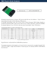


26-pin 2.54 mm NXP ColdFire Debug Adapter
Ordering code
IC50130
This debug adapter is used to connect the iC5000 BlueBox to NXP ColdFire based target
featuring a 26-pin 2.54 mm pitch target debug connector with the ColdFire pinout.
This debug adapter is supported by the iC5000 BlueBox only.
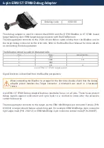
The debug adapter connects to the 25cm 40-pin ribbon cable coming from the BlueBox and to
the target debug connector on the other side. Refer to the BlueBox User Manual for more details
on connecting the debug adapter.
The following pinout is valid on the target side:
Signal direction
Signal
Pin
Pin
Signal
Signal direction
I
Developer Reserved
1
2
~BKPT
O
GND
3
4
DSCLK
O
GND
5
6
Developer Reserved
RESET
7
8
DSI
O
I
VDD_IO
9
10
DSO
I
GND
11
12
PSTDDATA7
I
I
PSTDDATA6
13
14
PSTDDATA5
I
I
PSTDDATA4
15
16
PSTDDATA3
I
I
PSTDDATA2
17
18
PSTDDATA1
I
I
PSTDDATA0
19
20
GND
Motorola Reserved
21
22
Motorola Reserved
GND
23
24
PSTCLK
I
I
NC
25
26
~TEA
O
26-pin ColdFire target pinout
Blue colored signals are trace signals.
Signal Direction is described from the BlueBox perspective.
When connecting the BlueBox to a target for the first time, double check that the debug
adapter pinout matches the Target connector. A mismatch can result in a hardware
failure.
26-pin 2.54 mm NXP ColdFire Debug Adapter features resettable fuses on pins 2, 4, 7, 8, 9, 10,
24 and 26. These protect debug signals against overcurrent and cycle back to a conductive