TASKING iSYSTEM IC50130 Скачать руководство пользователя страница 16

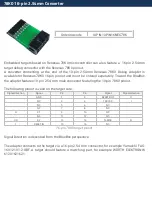
10-pin 2.54mm Renesas 78K0 Debug Adapter

Ordering code

IC50174

This debug adapter is used to connect  the  iC5000 and the  iC5700 BlueBox  to  Renesas  78K0
based target featuring 10-pin 2.54mm pitch target debug connector with the 78K0 pinout.
The debug adapter connects to the 25cm 40-pin ribbon cable coming from the BlueBox and to
the target debug connector on the other side. Refer to the BlueBox User Manual for more details
on connecting the debug adapter.

The following pinout is valid on the target side: 

Signal direction

Signal

Pin

Pin

Signal

Signal direction

I

RESET IN

1

2

RESET OUT

O

O

FLMD0

3

4

TARVCC

I

I/O

X2

5

6

GND

O

X1

7

8

GND

I

NC

9

10

5V OUT

O

10-pin 78K0 target pinout

Signal Direction is described from the BlueBox perspective.

When connecting the BlueBox to a target for the first time, double  check  that  the  debug
adapter  pinout  matches  the  Target  connector.  A  mismatch  can  result  in  a  hardware
failure. 

If  the  ‘Supply  5V  to  the  target’  option  is  checked  in  the  ‘Hardware/Emulation  Options/CPU
Setup/Advanced’ tab, the debugger supplies 5V at the ‘5V OUT’ pin (pin 10) on the target debug
connector, which can be used to power the target. Maximum target current consumption should
not exceed 50mA.

If  ‘RESET  IN’  (target  reset  detection)  from  the  microcontroller  is  not  connected  to  the  target
debug connector pin 1, 10k ohm pull-up  must  be  connected  to  this  pin  or  the  debugger  may
exhibit unpredictable behavior.

10-pin 2.54mm Renesas 78K0R Debug Adapter features resettable fuses on all connected pins.
These protect debug signals against overcurrent and cycle back to a conductive state after the
excessive current fades away.

The  debug  adapter  connects  to  the  target  via  a  10-pin  2.54  mm  connector,  for  example
Yamaichi FAS-1001-2101-2-OBF. A target should feature a matching part, for example WÜRTH
ELEKTRONIK 61201021621.

Содержание iSYSTEM IC50130

Страница 1: ...Legacy Debug Adapters User Manual V1 5 August 2023 isystem com start...

Страница 2: ...otential damage caused by any voltage difference between the device and the target system Use proper overvoltage protection Ensure proper protection to avoid exposing the BlueBox device or the operato...

Страница 3: ...bug Adapter 8 16 pin 2 54mm NXP COP Debug Adapter 9 38 pin Mictor PPC4xx RISCTrace Debug Adapter 10 16 pin 2 54mm Renesas 78K0R Debug Adapter 12 26 pin KEL Renesas V850 Debug Adapter 14 20 pin 2 54mm...

Страница 4: ...2 288 or older Ordering Code Description IC50130 26 pin 2 54 mm NXP ColdFire IC50140 6 pin 2 54mm NXP BDM IC50141 6 pin 2 54mm NXP S12Z BDM IC50153 16 pin 2 54mm NXP COP IC50155 38 pin Mictor PPC4xx R...

Страница 5: ...ion I Developer Reserved 1 2 BKPT O GND 3 4 DSCLK O GND 5 6 Developer Reserved RESET 7 8 DSI O I VDD_IO 9 10 DSO I GND 11 12 PSTDDATA7 I I PSTDDATA6 13 14 PSTDDATA5 I I PSTDDATA4 15 16 PSTDDATA3 I I P...

Страница 6: ...s on pins 1 12 19 and 24 are protected via 47 ohm serial resistors The debug adapter connects to the target via a 26 pin 2 54 mm connector for example Yamaichi FAS 26 17 A target should feature a matc...

Страница 7: ...ction Signal Pin Pin Signal Signal direction I O BGND 1 2 GND NC 3 4 RESET I O NC 5 6 VTref I 6 pin BDM pinout Signal Direction is described from the BlueBox perspective When connecting the BlueBox to...

Страница 8: ...debug connector on the other side Refer to the BlueBox User Manual for more details on connecting the debug adapter The following pinout is valid on the target side Signal direction Signal Pin Pin Si...

Страница 9: ...RST O I HALTED 5 6 VTref I O TCK 7 8 CKSTP_IN O O TMS 9 10 NC O SRESET 11 12 GND O HRESET 13 14 NC I CKSTP_OUT 15 16 GND 16 pin COP target pinout Signal Direction is described from the BlueBox perspec...

Страница 10: ...apter The following pinout is valid on the target side Signal direction Signal Pin Pin Signal Signal direction NC 1 2 NC NC 3 4 NC GND 5 6 TRCLK I O HALT 7 8 NC O SRST 9 10 NC I TDO 11 12 VREF I NC 13...

Страница 11: ...back to a conductive state after the excessive current fades away Signals on pins 6 25 26 27 28 29 30 31 32 33 34 35 36 37 and 38 are protected via 47 ohm serial resistors The debug adapter connects t...

Страница 12: ...out Signal Direction is described from the BlueBox perspective When connecting the BlueBox to a target for the first time double check that the debug adapter pinout matches the Target connector A mism...

Страница 13: ...The debug adapter connects to the target via a 16 pin 2 54 mm connector for example Yamaichi FAS 1601 2101 2 OBF A target should feature a matching part for example W RTH ELEKTRONIK 61201621621...

Страница 14: ...und 13 14 DDI O Ground 15 16 DCK O Ground 17 18 DMS O Ground 19 20 DDO I Reserved 21 22 DRST O Reserved 23 24 RESET O I Reference Voltage 25 26 FLMD0 O 26 pin V850 target pinout Signal Direction is de...

Страница 15: ...nRESET CPU Reset I O Ground GND 13 14 FLMD0 Flash Mode O Ground GND 15 16 nRDY Synchronizatio n I Ground GND 17 18 TDO JTAG I Ground GND 19 20 Vref Reference Voltage I 20 pin V850 target pinout Signal...

Страница 16: ...heck that the debug adapter pinout matches the Target connector A mismatch can result in a hardware failure If the Supply 5V to the target option is checked in the Hardware Emulation Options CPU Setup...

Страница 17: ...adapter features 10 pin 2 54 mm male connector featuring the 10 pin 78K0 pinout The following pinout is valid on the target side Signal direction Signal Pin Pin Signal Signal direction GND 1 2 RESET...

Страница 18: ...O 4 pin ERNI ST STM8 target pinout Signal Direction is described from the BlueBox perspective When connecting the BlueBox to a target for the first time double check that the debug adapter pinout matc...

Страница 19: ...www isystem com Visit our website for Support isystem com support Tutorials isystem com getting started Knowledge Base kb isystem com...

Отзывы: