14
The Porta-Tile is designed for use with a
TARGET®
6"
Profile Wheel, such as P/N 621081 or 621082. (See Fig. 1)
Raise the Blade Guard (K). Remove the Blade Shaft
Nut (N) and Outer Flange (M). Remove the tile saw
blade if one has been installed.
Install the profile wheel onto the spindle shaft up against
the Inner Flange with the working surface to the out-
side.
Secure into place by reversing the Outer Flange (M)
and tightening the Blade Shaft Nut (N). Lower the Blade
Guard (K) back down over the profile wheel. Adjust Blade
Guard as needed to best center profile wheel in the
guard.
Locate the material for profiling:
1.
Set the edge of the part to be shaped parallel to
the wheel.
2.
Locate the material under the wheel. Pull the
Conveyor Cart (4) with the material from under the
wheel to set proper cutting height.
Your
Porta-Tile II
tile saw is factory assembled and aligned
prior to shipment to ensure accurate cuts when your saw is
delivered. However, since
TARGET®
cannot control rough
handling during shipping, it is suggested that the alignment
be checked. If the saw is found in need of adjustment, refer
to the appropriate section(s) below.
There are two basic alignment checks for the
Porta-Tile
and
any adjustments made must follow these procedures to
ensure that the unit functions freely. Always unplug the saw
before performing any alignments.
Adjustment tools required: Carpenters Square, a 1/2 wrench
and a 5/32 Hex Key wrench.
2.
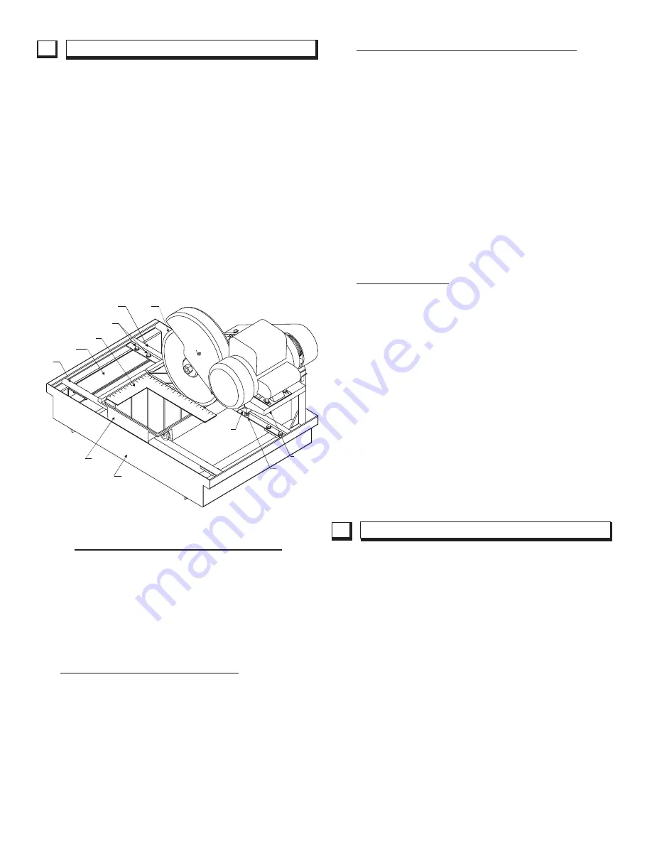
Check the Parallel Alignment (See Figure 2)
*
The Conveyor Cart should travel parallel to the
plane of the blade. The Blade should not set at an
angle to the cut line through the tile.
*
Place a square rule against the backstop, lightly in
contact with the blade. The blade surface should
be parallel to the square; i.e., no gap between the
blade and the square at either the front or back
edge of the blade. (It is important that the blade
be flat. To check, slowly rotate the blade by hand
with the square lightly contacting it.) Next, holding
the square firmly, traverse the cart fore and aft.
The blade should remain parallel to the square,
staying slightly in contact with it throughout its full
travel. If the blade does not stay in contact with
the square, the Parallel alignment must be per-
formed.
Parallel Alignment
*
The parallel tracking of the Cart can be adjusted
by squaring the Rails (R) to the Frame which hold
the Cutting Head Assembly. It is helpful to align
one rail first and then use the cart to set the sec-
ond rail parallel to the first. The holes in the rails
are larger enough to accommodate any adjustment
needed.
*
A good practice is to align the INNER RAIL first.
Loosen the eight (8) 5/16"-18 capscrews (1/2"
wrench) locating the two (2) Rails (R) so that both
rails are free to move. Move the end(s) of rail until
the square is flush with the blade as described
above. Tighten the fasteners of this rail and re-
check the alignment. Once alignment has been
made, move the cart fore and aft to locate the
second rail parallel to the first. Tighten the remain-
ing fasteners.
1
.
Check the Blade in Slot Alignment
*
The blade should be centered in the conveyor cart
slot.
*
Set-up your saw as described above and move the
conveyor cart back and forth from the front to the
rear of the pan. If the blade contacts either side of
the slot, the Cutting Head Location Adjustment must
be performed.
Cutting Head Location Adjustment (See Figure 1)
*
The Cutting Head Assembly is located along the
Pivot Bar (A). Using a 1/2 wrench, loosen the four
5/16 capscrews holding the two Bearing Caps (B).
Also, with a 5/32 Hex Key, loosen the two Set Col-
lars (S). Move both the Set Collars and Head As-
sembly along the bar until the blade is centered in
the slot. Re-tighten the Set Collars and four 5/16
capscrews.
FIGURE 2
7
ALIGNMENT PROCEDURES
8
PROFILE WHEEL SET-UP AND USE
5/16”-18
FASTENERS
B
BEARING CAP
(8) 5/16”-18
FASTENERS
R - RAIL
INNER
SQUARE
R
RAIL
CART
PAN
MOTOR
BASE
RAIL
SUPPORT
BLADE
Содержание PORTA-TILE II
Страница 17: ...17 NOTES ...
Страница 30: ...30 Diagram 2 Wiring Diagram 169422 ...
Страница 31: ...31 Diagram 3 Wiring Diagram 000503 ...
Страница 32: ...32 NOTES ...


