12
full length and retighten knob. (As shown in Figure
A)
2. Make sure the extension cord is not tangled and is
free from the machine. (Electric Models only.)
3. With the handle positioned down, confirm that the
blade is clear of the surface.
A. Turn switch to “ON” position (Electric)
B. Start the engine (Gas)
4. Align the saw with the cutting line using the front
and rear pointers as references.
5. The blade on this saw may be lowered in the
concrete by loosening the lock knob and allowing
the weight of the saw to assist in the lowering of the
blade. DO NOT push the handle forward. The
blade is held at the desired depth by tightening the
lock knob when the blade has reached the desired
depth. The saw can now be raised form the cut and
will return to the previous preset depth.
6. Raise the handle and the blade will plunge to the
preset depth. The depth can be preset to any depth
between 0 and 2 by adjusting the depth stop.
Loosen the depth stop knob and slide stop up or
down to achieve the desire depth. Push the saw
with even steady pressure. Maintain proper cutting
speed by listening to the motor or engine. Should
the blade slow or stall, reduce forward pressure and
allow the blade shaft speed to recover.
6. Application
Guide
A. INTRODUCTION:
•
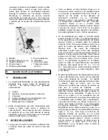
The MICROCON saw has been specifically
designed to cut expansion joint in concrete. It is
designed with the following features:
A. Portable
B.
Option - Gas or Electric Versions
C. Compact
D.
Variable Depth Control
E.
Stable Cutting Platform
F. Counterbalanced
•
These features have been incorporated to aid in
achieving straight and acceptable cuts in green
concrete. However, just as finish troweling is an art
to achieve the desired texture, so is cutting green
concrete an art to achieve straight and spall free
joint.
B
.
READING THE CONCRETE:
•
After the concrete has been final troweled, the joints
should by cut as soon as possible.
•
Many factors effect the time of cutting as with
troweling. They are water content of the mix, SPI
rating of the mix, size of the aggregate, type of
surface finish desired, i.e., broomed, hand troweled,
power troweled, and super finish. Ambient air
temperature, humidity, direct sunlight and many
other atmospheric conditions can effect the curing
rate as well. Therefore, no hard and fast rules can
be established to assure optimum cut quality and
speed. Only experience.
•
It has been found that sealing the concrete can aid
in improving the cut as well as speed clean up. It is
suggested that if the job specification calls for
sealing, the sealant should be applied prior to
cutting. This may delay the cutting while the
sealant is curing. However, it will proved easier
clean up. Here again, conditions on specific jobs
may change this approach, but in general, it is
recommended to apply the sealant first.
•
Next, chalk a line. Align the front and rear pointer
on the chalk line and cut with steady even pressure,
not stalling the engine during the cut. Cut only as
deep as the job specification requires! Set the
depth stop so as to maintain the required depth of
cut. This can be between 1/2 & 2 (1.2 & 5 cm).
Remember deeper cuts mean slower cutting rate
and additional blade wear and cost.
•
Many job specifications now allow shallow cuts for
crack control when cut within a few hours of the
pour. A certain amount of random cracking may be
controlled during the initial curing process, but there
is no scientific data to ascertain effectiveness of the
crack control. Job specifications, requiring early
cutting within a few hours of the pour are being
based on contractor input. If this is not verified in
your region and not consistent with field condition, it
is strongly suggested that the contractor request
deviation to the specification. The first 60 days are
critical as well as the first thermocycle (weather
related temperature changes). The TARGET
MICROCON has sufficient power and head weight
to maintain a constant depth up to 2 (50mm).
This can assure random crack control within the
long established guide line of D/4 in a slab up to 8
(15cm) thick. Unless otherwise specified, the D/4
principal should be followed and cutting the full D/4
with the MICROCON, it is not necessary to recut
the joint the next day.
C
.
IF UNACCEPTABLE SPALLING OCCURS,
THERE ARE SEVERAL ITEMS TO
INVESTIGATE:
•
Check for excessive movement in the front axle.
Adjust set collar so the front axle moves freely, but
has no excessive play. Adjust set collars so there
is no play in the handle and rear wheels as well.
Содержание MICROCON MCC 75E
Страница 7: ...7...
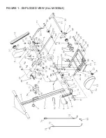
Страница 20: ...FIGURE 1 EXPLODED VIEW ALL MODELS...
Страница 23: ...23...
Страница 24: ...24 Rev 1 22August2002 Item 49 Pg21 Figure 1 Parts List 020136 Qty 2 Was 14432634 Qty 4 In Error Ref ECO 6235...


