Tarana Wireless, Inc. Proprietary and ©2021. All rights reserved. vG1-RN-2021-01
G1 RN Manual — 13
Installing the RN
Step 1.
Attach the ground system to the chassis first! There is a stainless screw
installed on the RN that is used for attaching the ground.
o
Ground wire should be 14AWG (2.5mm2)
o
A ring terminal suitable for the M5 screw should be crimped to the
ground wire.
o
Torque screw to 6 N-m (4.5 ft - lb)
o
Grounding wire shall not limit any adjustment needed or
alignment.
Additional local electrical codes and ordinances may apply to
grounding. Compliance in this area is the responsibility of the
installation company and not Tarana Wireless Inc.
Step 2.
Install the body of the cord grip into the RN enclosure. Take care not to
cross thread the plastic threads of the cord grip body with the aluminum
threads of the RN enclosure.
Step 3.
Properly terminate and test Ethernet cable run before proceeding. This
should include power verification on all pins of the Ethernet cable using a
POE tester.
Step 4.
With POE power disconnected, slide the cord grip sealing nut and split
gland over and around the terminated RJ45 connector and cable.
Step 5.
Carefully plug the RJ45 connector into the RN making sure there is an
audible click made by the connector properly seating into RJ45 receptacle
on the main PCB inside the RN enclosure. If the click is not heard a slight
pull on the Ethernet cable is sufficient to check if the cable has been
properly seated or not. DO NOT FORCIBLY pull on the Ethernet cable as it
could cause irreparable damage to the PCB.
Step 6.
With the Ethernet cable connected, slide the split gland and sealing nut
down the Ethernet cable towards the RN and into place.
Step 7.
While tightening this assembly together make sure that the Ethernet cable
is not being twisted in any way in the process.
Step 8.
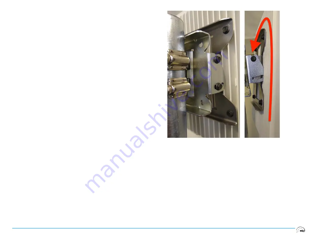
Install RN by lowering it onto the elevation bracket such that the partially
threaded-in screws are captured by the U-shaped features on the bracket.
Tighten the top screw on each side of the mount enough to prevent the RN
from coming loose while performing the next steps.
Step 9.
Align the tilt adjustment slot so that the threaded holes in the elevation
attachment tabs of the chassis bracket tabs are accessible and install the
two lower screws (one on each side) and snug them. Final torque
sequence will follow after final alignment and pointing.
Содержание G1 RN
Страница 1: ...TaranaG1RNManual ...


