background image

04_ ECLIPSE MANUAL

FITTING OF ACCESSORIES

Check the following accessories are present in the carton, according to model:

•  ONE, MINI & CENTRE: Self adhesive feet x 4
•  TWO & THREE: Plinth sections x 2, plinth mounting screws x 4, carpet spikes x 4, locking nuts x 4, spike  


  locating cups x 4
 

ONE, MINI & CENTRE

The supplied self-adhesive feet may be fitted to the underside of the loudspeaker to prevent slipping and avoid  
damage to the surface of the shelf or stand. The tweeter should be roughly at ear height when seated in the chosen 
listening position.

TWO & THREE: FLOOR STANDING MODELS

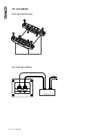
The Eclipse floor standing models perform best with the plinth and carpet piercing spikes fitted, giving optimum stability 
and sound quality. First fit the plinth sections to the underside of the loudspeaker with the 4 screws provided, taking 
care not to over tighten. The spikes provided, along with lock nuts, should be inserted into the threaded holes in the 
underside of the plinth. Level the speaker and then tighten the lock nuts firmly but without using undue force. Spike 
locating cups are provided in the accessory pack and these may be used to protect sensitive floor surfaces. (See fig. 1)

WARNING:

Ensure that the spikes are levelled and that the lock nuts are tightened firmly. The spikes should be pushed through the 
carpet to locate into the flooring surface by applying pressure to the top of the cabinet.
If using on a sensitive floor surface place the protective cups under the levelled spikes. Failure to do so could render the 
speaker unsteady and result in damage or injury should it be knocked over.

CONNECTION

To avoid potential damage to your loudspeaker, ensure that the amplifier is switched OFF prior to connecting or 
disconnecting any cables. Before switching on double check that all connections are secure and that polarity is correct.

•  The positive (plus) terminal on the amplifier left channel ( or coloured red) must be connected to the  


  positive HF terminal on the left speaker. The left speaker is the one on the left as you look at the stereo pair from    
  your listening position.

•  The negative (minus) terminal on the amplifier left channel (marked - or coloured black) must be connected to the  
  negative HF terminal on the left speaker.

•  Repeat this connection process for the right speaker. Remember that the positive (+ or red) on the amplifier must    
  be connected to the positive (+ or red) on the speaker and the negative (- or black) to negative.

•  Select a signal source, such as a CD player; switch on the amplifier and slowly turn up the volume control to check  
  that both loudspeakers are reproducing bass and treble information. (See fig. 2)

Содержание Eclipse

Страница 1: ...OWNER S MANUAL ...

Страница 2: ...dspeaker is necessary As part of the MUSIC Group Tannoy is committed to providing the highest quality products service and user experience for our customers One element of this commitment is our after sales support which now incorporates our extended Limited Warranty In the event of any concern that is not addressed by this extended Limited Warranty we would ask you to contact us at care music gro...

Страница 3: ...ut signal This if done for any extended period will cause damage to the speakers Generally an amplifier of higher power that is running hard but free of distortion will do less damage to the loudspeaker than a lower power amplifier continually clipping Remember also that a high powered amplifier running at less than 90 of output power generally sounds a great deal better than a lower powered examp...

Страница 4: ...ed and that the lock nuts are tightened firmly The spikes should be pushed through the carpet to locate into the flooring surface by applying pressure to the top of the cabinet If using on a sensitive floor surface place the protective cups under the levelled spikes Failure to do so could render the speaker unsteady and result in damage or injury should it be knocked over CONNECTION To avoid poten...

Страница 5: ...th the ability to treat the subwoofer as a single discreet channel for special effects playback or for music applications as a dedicated low frequency instrument channel This places new demands on the surround and centre channel loudspeakers in both the mixing environment and the playback environment The 5 1 format allows the mix engineer in the recording studio to assign audio information to one ...

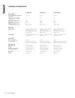
Страница 6: ...dymium magnet system Low frequency 127 mm 5 Multi fibre coated pulp paper cone 127 mm 5 Multi fibre coated pulp paper cone 127 mm 5 Multi fibre coated pulp paper cone x 2 CROSSOVER Crossover frequency 3 2 kHz 3 2 kHz 3 2 kHz Crossover type Passive low loss 2nd order low pass 3rd order high pass Passive low loss 2nd order low pass 3rd order high pass Passive low loss 2nd order low pass 3rd order hi...

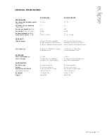
Страница 7: ...urethane damped layer woven polyester dome neodymium magnet system Low frequency 100 mm 4 Multi fibre coated pulp paper cone 2 x 100 mm 4 Multi fibre coated pulp paper cone CROSSOVER Crossover frequency 2 2 kHz 2 4 kHz Crossover type Passive low loss 2nd order low pass 3rd order high pass Passive low loss 2nd order low pass 3rd order high pass CONSTRUCTION Enclosure type Rear ported reflex Rear po...

Страница 8: ...08_ ECLIPSE MANUAL SET UP DIAGRAMS Fig 1 Eclipse Plinth Assembly Fig 2 Connection All Models POWER AMPLIFIER L R SPEAKER TO RIGHT ...

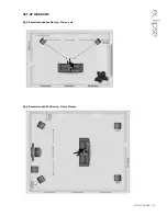
Страница 9: ...ECLIPSE MANUAL_09 SET UP DIAGRAMS Fig 3 Recommended positioning Stereo pair Fig 4 Recommended Positioning Home Cinema ...

Страница 10: ...010_ ECLIPSE MANUAL NOTES ...

Страница 11: ...ECLIPSE MANUAL_011 NOTES ...

Страница 12: ...erates a policy of continuous research and development The introduction of new materials or manufacturing methods will always equal or exceed the published specifications All specifications are subject to change without notice Copyright c 2015 Music Group Innovation SC Ltd All rights reserved ...

Отзывы: