Introduction
Reference Guide: SM6610, SM6615, SM6620 and SM6625 Satellite Modulators
Page 1-11
ST.RE.E10152.2
1.7.3
Rear Panel Connectors
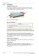
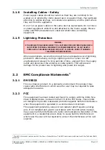
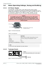
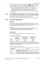
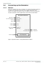
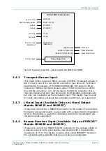
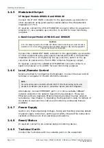
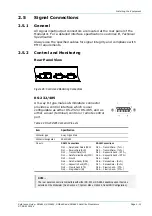
All input and output connectors are located at the rear panel (see
Figure 1.5 to Figure 1.8).
For pin-out information, see Chapter 2, Installation. For specifications of
the connector interfaces, see Annex B, Technical Specification.
Figure 1.5: View of the SM6610 Modulator Rear Panel
Figure 1.6: View of the SM6615 Modulator Rear Panel
Figure 1.7: View of the SM6620 Modulator Rear Panel
Figure 1.8: View of the SM6625 Modulator Rear Panel
1.8
Input Option Module
The SM6600 Satellite Modulator chassis design allows the fitting of an
input option module, providing the capability for the Modulator to accept
input data streams in alternative formats. The following options are
currently available:
•
DVB ASI & SPI Input Card (S13450)
1.9 Getting
Started
The following check list provides a guide as to what needs to be done to
get the equipment up and running.
Содержание SM6610
Страница 10: ...Introduction Page 1 2 Reference Guide SM6610 SM6615 SM6620 and SM6625 Satellite Modulators ST RE E10152 2 BLANK...
Страница 138: ...Equipment Description Page 7 2 Reference Guide SM6610 SM6615 SM6620 and SM6625 Satellite Modulators ST RE E10152 2 BLANK...
Страница 172: ...Licence Keys Page 10 2 Reference Guide SM6610 SM6615 SM6620 and SM6625 Satellite Modulators ST RE E10152 2 BLANK...

