


TX7331 Intelligent Graphic Repeater Panel
Installation & Operation Manual
4050100365-Rev1.1-1117
TANDA UK
Specifications are subject to change without prior notice
9
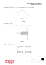
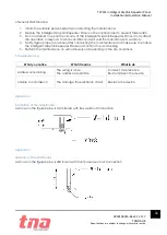
DI+, DI-, DO+, DO-: 24DC power supply wiring terminal, non polarized.
3 Operation
3.1 Preparation
The TX7930 handheld programmer is used to configure Intelligent Graphic Repeater Panel soft
address. This tool is not included, must be purchased separately. The programmer is packed with
twin 1.5V AA battery and cable, ready for usage once received.
It is mandatory for the commissioning personnel to have programmer tool in order to adjust the
Intelligent Graphic Repeater Panel conferring to the site situation and environmental requirements.
Program a unique address number for each device according to the project layout before placing
from the Terminal Base.
Warning:
Disconnect the loop connection whilst connecting to the handheld programmer.
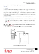
3.2 Repeater Addressing
1.
Connect the programming cable to ZI+ and ZI- (or ZO+ and ZO-) terminals
(Figure 9)
. Press
“Power”
to switch on the unit.
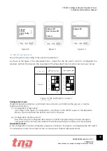
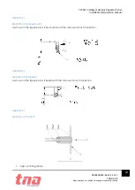
2.
Switch-on the programmer, then press button
“Write”
or number
“2”
to enter Write
Address
mode
(Figure 10).
3.
Input the desire device address value from 1 to 254, and then press
“Write”
to save the new
address
(Figure 11)
.
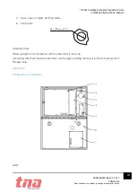
Note:
If display
“Success”,
means the entered address is confirmed. If display
“Fail”,
means failure to
program the address (
Figure 12)
.
4.
Press
“Exit”
key to go back Main Menu. Press
“Power”
key to switch-off the programmer.
Figure 9: Programmer Connection Detail