AIR-IQ2 AIRFLOW MEASUREMENT SOLUTION
T.A. Morrison & Co. Inc. | P.O. Box 157 Smiths Falls Stn Main, Ontario, Canada K7A 4T1 | 800 561 3449 | Fax: 800 668 8476 | tamcodampers.com
EBTRON, Inc. | 1663 Hwy. 701 S., Loris, SC USA 29569 | 800.2EBTRON (232.8766) | Fax: 843.756.1838 | www.ebtron.com
AIR-IQ2 INS
TALL GUIDE_2022_04
8
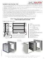
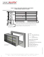
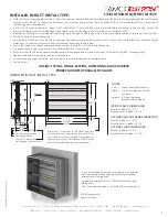
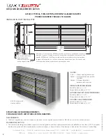
AIR-IQ2: TYPICAL, TWO-SECTION, HORIZONTAL-BLADE DAMPER
PROBES MOUNTED PARALLEL TO BLADES
INSTALLED IN DUCT INSTALL TYPE
INSIDE SLEEVE DIMENSIONS:
Parallel to blade = A - 2.5"
Perpendicular to blade = B - 2.5"
OUTSIDE DAMPER FRAME DIMENSIONS:
Parallel to blade = A - 0.5"
Perpendicular to blade = B - 0.5"
OUTSIDE FLARE DIMENSIONS:
Parallel to blade = A - 0.5"
Perpendicular to blade = B - 0.5"
*NOTES:
A x B: = Always opening dimensions
Width = A: Always dimension parallel
to blades
Height = B: Always dimension
perpendicular to blades
AIR-IQ2 shown with
sleeve and flare
B - 2.5”
1"
¼"
1"
¼" clearance
B
Non-ducted applica�on
4"
5"
6"
5.1" 2.4"
12.5"
Ducted applica�on
13.5"
Minimum distance to
trailing edge of intake louver
9"
B*
B
-
0.5”
1"
A - 0.5”
A - 2.5”
A*
1"
4"
Minimum 4" clearance for EBTRON insertion style sensor probes and electronic
actuator. Does not include access for wiring after installation of assembly.
See
specific EBTRON and TAMCO series technical documentation
for
more information.
Jumpers will always be on the face of damper, downstream from the louver, and
will ship with all damper units that are two sections wide.
Airflow
STRUCTURAL DESIGN REQUIREMENTS
FOR AIR-IQ2 UNITS WITH TWO-SECTION DAMPERS
REQUIREMENTS:
•
Tubular or angled steel, structural support is required to resist applied pressure loads for AIR-IQ2 units with two-section dampers.
MAXIMUM DEFLECTION:
•
The structure providing intermediate support must be designed to resist the highest pressure load, with deflection of less than L/230. This applies
whether the pressure load is created by the mechanical system, or by wind load, or if the damper is mounted on the exterior of the building.


