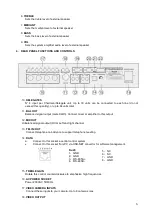
background image

8

6. INSTALLATION AND CONNECTION

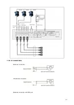
Connect the unit to 230 V AC 50/60 Hz mains. Use the connection cables provided to connect the daisy-

chained microphone units to the 4

Delegates outputs

, paying attention not to connect more than 30

microphones units to each line and no more than 64 microphone units altogether.

The configuration cannot allow more than 30 microphone units on each loop.

In any case, the maximum limit of 64 microphone units cannot be exceeded.

The system can host more than one Chairman microphone. They can be inserted at any position on the

chain.

1

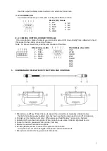
- Prepare conference controller, chairman microphone, delegate microphone, main extension cable

and microphone branch cable (Y type)

- The controller is supplied with a main extension cable (13 m with one male DIN-8 connector for

connection to the controller, one female DIN-8 connector for connection to the microphone Y type

branch cable), one male-female XLR cable, one RCA-6.3 mm jack audio cable and one power

cable

13 m

- Chairman microphone and delegate microphone are supplied with a branch/interconnection Y

type cable (2+1.5 meters) with one female DIN-8 connector for connection to the main extension

cable or to the previous microphone, 2 male DIN-8 connector for connection to microphone and

extend the line to the next microphone

2

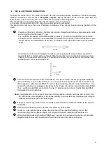
Connect the main extension cable (male DIN-8 13 m) to one of the sockets group (DELEGATES)

of the controller. In each of the 4 lines you can connect 30 mics maximum. Connect the other end

of the extension cable (female DIN-8 13 m) to Y type microphone branch cable (male DIN-8 2 m),

connect the chairman or delegate microphone to the Y type microphone branch cable (male DIN-8

1.5 m), and the male DIN-8 connector to the next Y type microphone branch cable (female DIN-8

2m) to extend the microphones

Note:

Paying attention not to connect more than 30 microphones units to each line and no more than

64 microphone units altogether, microphone quantity in one system may decreased according to

different microphone type and cable length.

3

If desired, contact any of the line-level outputs (balanced XLR or unbalanced RCA) to the input of

an amplifier.

4

Connect the controller to 230 V AC 50/60 Hz mains by power cable.

5

To talk on a microphone, please press the on/off key. When you finish talking, turn off the

microphone by pressing the key again. If microphone is active, indicator light switches on.

6

When chairman press and hold the PRIOR key 1 second on chairman microphone unit, all active

delegate microphones will be switched off and the chairman microphone will active.

Содержание DG-S100

Страница 1: ...OWNER S MANUAL DIGITAL CONFERENCE SYSTEM...

Страница 2: ...ANEL FUNCTIONS AND CONTROLS 6 5 CHAIRMAN AND DELEGATE UNIT FUNCTIONS AND CONTROLS 7 6 CONNECTION AND INSTALLATION 8 7 HOW TO USE THE SYSTEM 11 8 FRONT PANEL FUNCTIONS AND CONTROLS 12 9 R E A R P A N E...

Страница 3: ...nd user s instructions must be followed Sentences preceded by symbol contain important safety instruction Please read it carefully DETAILED SAFETY INSTRUCTIONS Water and moisture This apparatus should...

Страница 4: ...g is damaged If liquid has spilled or objects have fallen into the unit The unit has been exposed to rain The unit doesn t operate normally or exhibits a marked change in performance If the product ha...

Страница 5: ...several expansion units Every expansion unit can support up to 60 units divided on six lines never use more than 30 units on each line Adding four expansion units the system can control up to 254 uni...

Страница 6: ...d signal output male XLR3 Connect mixer or amplifier to this output 12 MIX OUT Unbalanced signal output RCA Left and right channel 13 TEL IN OUT Connect telephone coincidence to support telephone meet...

Страница 7: ...d unless the limit of simultaneously enabled units has been reached press again to turn off microphone 2 Priority key for chairman unit only When press and hold this key 1 second on chairman 3 Indicat...

Страница 8: ...previous microphone 2 male DIN 8 connector for connection to microphone and extend the line to the next microphone 2 Connect the main extension cable male DIN 8 13 m to one of the sockets group DELEG...

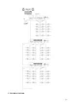
Страница 9: ...9 For discuss function For discuss Video tracking function...

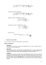
Страница 10: ...10 TYPE OF CONNECTIONS Balanced connection Unbalanced connection Balanced connection with TRS jack...

Страница 11: ...hat can speak simultaneously Once this number of delegates is reached no further delegates will be allowed to intervene until the number of active delegate units again falls below this limit FIFO MODE...

Страница 12: ...ODE All activated DELEGATE units will be automatically disactivated after 45 seconds of inactivity In order to speak again the delegate will have to press MIC ON OFF again A OFF MODE X There are no ti...

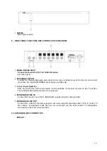
Страница 13: ...er Switches After connecting the units to the system set the switches of the lines involved on the I position The LED light will indicate that the line is powered 4 EXSPANDER LINK IN Connect this inpu...

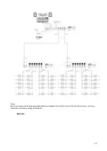
Страница 14: ...14 Note Be sure to keep the shortest possible distance between the central unit and the last microphone For long distances we advise opting for method 1 Method 2...

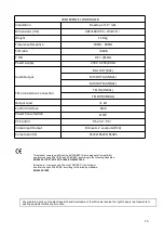
Страница 15: ...15 11 TECHNICAL FEATURES...

Страница 16: ...S 232 PC Video Input Output 8 xInputs 2 xoutputs RCA Camera Control RS232 RS422 RS485 This product complies with Directive 89 336 EEC Electromagnetic Compatibility and later changes 92 31 EEC and 93 6...

Отзывы: