


4
INSTALLATION
3
WIRING
2
CAUTIONS ON INSTALLATION
−
+
Power
10.5V to 30VDC
(non-polarity)
Alarm
NC
NO
COM
Alarm output
Dry contact relay
output 1c N/O-N/C
NC
Tamper output
Dry contact relay
output 1b N/O
When cover is
detached
●
Example connection 1
●
Example connection 2
●
Example connection 3
Power
Alarm(1ch.)
Alarm(2ch.)
Power
Alarm
signal
Power
Alarm
signal
Control panel
(12VDC)
Control panel
(12VDC)
Control panel
(12VDC)
①
Remove cover from
unit and slide the
mounting plate
upwards to detach
it.
②
Pull the wire through on the installation site.
③
Make one hole in the grommet on the mounting plate and
pull the wire through it.
Secure the plate with 2 x (
φ
4x30mm) self-tapping screws.
④
When the wiring is exposed break knockouts (2 positions) on
the rear of the unit, pull the wire through as in the figure
and attach it to the terminals on the sensor.
Wiring from
the bottom
Wiring from
the top
Knockout
Knockout
※
The grommet is compatible with a wire of
φ
3mm (
φ
0.12")
to
φ
6mm (
φ
0.24") outer dia.
When a wire of more than
φ
6mm (
φ
0.24") outer dia. is
used, cut off the dotted line portion on the below figure using
pliers or the like.
Then use caulking to prevent insects from entering into the
unit.
5m (16.5')
11m (36.3')
0.15m (5.9")
0.33m (13")
A
POSITION OF INSTALLATION
① ② ③ ④ ⑤ ⑥ ⑦
▼
▼
Wire size
Voltage
DC24V
DC12V
1,700m (5,610')
2,800m (9,240')
4,200m (13,860')
5,100m (16,830')
150m (500')
300m (990')
450m (1,490')
550m (1,815')
AWG 22 (Dia 0.65mm)
AWG 20 (Dia 0.8mm)
AWG 18 (Dia 1.0mm)
AWG 17 (Dia 1.1mm)
①②③④
①②③④
①②③④
①②③④
①②③④
}
}
}
}
.
.
Reflector
Sensor
A
protection distance
▼
▼
▼
▼
CAUTIONS ON INSTALLATION
EXPANSION OF BEAM
±10°
±90°
Vertical
adjustment
screw
Horizontal adjustment
80 to 100cm
(31" to 39")
}
}
}
.
.
Outdoor 1 to 11m(3.3' to 36')
Indoor 1 to 15m(3.3' to 49')
●Sensor
・
Hazardous weather such
as heavy rain or frost may
cause false alarms.
Sensitivity allowance of
reflective type beam
sensors is comparatively
lower than that of
standard type beams.
・
Remove all
obstructions (trees,
clothes lines, etc.)
between sensor and
reflector.
・
Avoid strong light from the
sun, automobile headlights etc.
directly shining on sensor.
When strong light stays in the
optical axis for a long time, it
does not cause malfunction but
will affect the product life.
・
Do not install the unit
on places where it
may be splashed by
dirty water or direct
sea spray.
・
Do not install the
unit on unsteady
surfaces.
・
Do not place highly
reflective objects
between the sensor and
the reflector as they are
likely to create a
protection loop and
prevent the sensor from
making a detection.
PROTECTION DISTANCE
*
Protection distance (between sensor/reflector) should not exceed in the rated range.
The external range may be reduced due to
the possible effect of mist and fog, or frost,
rain, or condensation on the sensor unit
cover and reflector unit, which can cause
nuisance alarms.
*
Sensitivity allowance will be greatly
decreased when the protection distance
deviates from the rated range.
(See the sensitivity allowance-protection
distance curve for PB-11BE)
BEAM ALIGNMENT
・
Fine tuning using a volt meter is required. (See section 5)
HEIGHT OF INSTALLATION
Install the sensor at a height of 80 to 100cm (31
"
to 39
"
)
to catch a human target.
(Install vertically so that the center of the sensor
lens and middle part of the reflector assembly are
placed at the same height.)
Using the adjustments, the lens can move horizontally
(
±
90 degrees) and vertically (
±
10 degrees) allowing
the unit to work in all directions.
(example 1 to 3)
・
Avoid overhead wiring.
・
When installing indoors, wiring procedures
similar to those for telephone or intercoms
are acceptable. Outdoor wires should be
placed inside conduit, or underground
cable/metal shielded cable should be used.
Example 1
Example 3
(When BL-11 optional is used)
Example 2
*
The sensor and reflector units should be installed uprightly and vertically.
Make sure that the reflector's front side faces the sensor as illustrated.
Expansion of beam can be calculated as follows.
A=0.03
×
TERMINAL CONFIGURATION
Maximum wiring distance when two or more sets are
connected is the value above divided by the number of
sets.
●
Wiring distance
Note)
CONNECTION
WALL MOUNT
⑤
After wiring is completed, adjust alignment, attach cover
and check operation.
(Note : Sealing is not required around the unit due to
rain-proof construction.)
82.5mm (3.29")
holes
middle point of the
sensor lenses
Self-tapping screws
Pull the wire through the sensor body (back to front)
and attach it to the terminals on the sensor.
Grommet
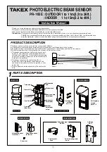
This beam sensor can be used for general monitoring, lighting control, and advising signalling (audible warnings, alarm ‘chime’
systems, or wired or wireless doorbells etc).
They are not recommended for ‘graded’ alarm systems, or perimeter or external detection in conjunction with security systems where
‘nuisance’ alarms are unacceptable.
For intruder alarm / security applications we recommend Takex active infra-red beams due to their increased stability and resistance
to nuisance alarms.
Sensitivity
allowance
Protection distance
1m
(3.3’)
11m
(36’)
15m
(49’)
●Sensor
●Reflector
●Reflector
In case of back-to-back
※
Fit pole size : Outside dia.38mm(1.5") to 45mm(1.77").
127mm(5”)
58mm(2.28”)
Hood fixing screw
Self-tapping screws
(
note
)
In case of outdoor installation, please do not remove hood.
(
note
)
It's not possible to mount the reflector back
to back.
(
note
)
It's not possible to mount the sensor on BL-11.
Self-tapping
screws
Screws
Push rivet
②
③
①
BL-11
Reflector
POLE MOUNT WITH BP-60A (Sold separately)
⑤
Please follow the wall mount procedure after completing the above.
Installation with BL-11 (Sold separately)
Self-tapping screws
196mm
(7.72”)
Hood fixing screws
Push rivet
Push rivet
Hood
①
②
③
④
Upside down
Oval countersunk head
screws
Screws
Pole bracket
Pole mounting plate
Sensor mounting plate
(Remove it from the sensor body)
①
②
③
④
Reflector
Oval countersunk head
screws
oval countersunk
head screws
Push rivet
Pole bracket
Pole mounting plate
①
②
③
④
①
Unscrew 2 x fixing screws on the top of reflector and remove the hood.
②
Remove push rivet.
③
Invert the reflector with the hood fixing holes facing downwards and fix into
position with 2 x
(
Φ
4x30mm)
self-tapping screws
using the upper
and lower holes.
④
Insert 2 x push
rivets into the
fixing screw holes
to cover these
holes.
※
In case of indoor installation, the hood can be removed if it is not required.
Fix the reflector into position
facing the sensor with
3 x (
Φ
4x30mm) self-tapping
screws
①
Insert 2 x oval countersunk head screws (M4x20) into the pole
bracket with a few turns.
②
Hold a pole between the pole mounting plate and the pole
bracket and tighten the screws.
③
Insert 2 x screws (M4x6) into the pole mounting plate with a
few turns.
④
Fix the sensor mounting plate to the pole mounting plate.
①
Mount the first pole mounting plate.
②
Pass through the second pole bracket under the
first pole mounting plate. and fix the second
pole mounting plate upside down.
※
Please follow the same procedure of wall mount
after above.
①
Fix the BL-11to the wall by 2 x self-tapping
screws.
(
Φ
4x20mm)
(using keyhole)
②
Fix the reflector to the BL-11 by 2 x oval
countersunk head screws (M4x20).
③
Insert the push rivet into the lower hole in
order to seal it.
①
Insert 2 x oval countersunk head screws (M4x20) into the pole
bracket with a few turns.
②
Hold a pole between the pole mounting plate and the pole
bracket and tighten the screws.
③
Fix the reflector unit to the pole mounting plate by 2 x oval
countersunk head screws (M4x20).
④
Insert the push rivet into the lower hole in order to seal it.
②
③
④