7
Instruction Manual MS-12TE & MS-12FE
We appreciate your purchase of a TAKEX passive
infrared sensor. This sensor will provide long and
dependable service when properly installed. Please
read this Instruction Manual carefully for correct
and effective use.
Please Note:
This sensor is designed to detect intrusion and to
initiate an alarm; it is not a burglary-preventing
device. TAKEX is not responsible for damage,
injury or losses caused by accident, theft, Acts
of God (including inductive surge by lightning),
abuse, misuse, abnormal usage, faulty installation or
improper maintenance.
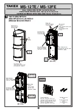
PRODUCT DESCRIPTION
The dual zone outdoor PIR is an automatic switch
which uses passive infrared sensor to detect infrared
(body temperature) emitted from a human body.
(Suitable for indoor/outdoor)
1)
This sensor is equipped with an "AND" detection
and pulse count system.
2)
The AND detection system will issue an alarm
signal only when detecion occurs in both horizon-
tal and downward zones simultaneously.
3)
The sensor is equipped with many features such as
Combining the sensor with other devices such as a
video monitoring system to display and record the
presence of an intruder.
The sensor can be combined with an audible or
visual warning device to annunciate the presence
of visitors.
2
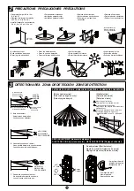
PRECAUTIONS
∗
Operation LED blinks for about 1min after turning
on power.
During this warm up period, the sensor does not
detect.
∗
This sensor operates during detecting time + delay
time (2 sec.)
It continues to issue an alarm as long as it detects
objects regardless of the set delay time.
∗
Do not pour water on this unit with a hose as it is
designed to be rainproof, not waterproof.
∗
When detection mode is set at AND mode, this
sensor outputs an alarm signal only when both
upper and lower sensor detect objects.
In other words, it won’t make detection in the area
which is not covered by both upper and lower sensor.
[Only applicable to MS-12FE]
[Detection area]
(The area covered by both
upper and lower sensor)
Lower sensor coverage
(No detection)
Lower sensor coverage
Upper sensor coverage
(No detection)
Upper sensor coverage
3
DETECTION AREA
The detection zone of this unit consists of a horizon-
tal zone and a downward zone.
Detection distance can be set by adjusting the angle
of downward zone.
MS-12TE is equipped with 1set of sensors on the
upper side.
MS-12FE is equipped with 2sets of sensors on the
upper and lower side, making it possible to select
AND mode or OR mode.
A. Alarm signal is issued only when both horizontal
and downward zone detect objects.
B. It does not detect small animals which are not
likely to reach the height of horizontal zone.
C. It does not detect vehicles moving in the area
outside the range of the downward zone.
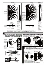
PATTERN OF COVERAGE
[Wide angle detection]
(1)
Point the sensor to the center of the area to be
detected. By turning the sensor up to ±45°, it can
detect all zones in front of it.
When the unit is turned more than ±45°, detection
zone will be eliminated one by one from the end.
(2)
It consists of seven detection zones.
(Wide angle: 90°)
(3)
Utilize attached area masking sheet when elimi-
nating detection zones.
[Wall detection]
(1)
Attach area masking sheet to the lens holder
(inside the cover) without cutting it out.
(Refer to
5
AREA MASKING SHEET.)
(2)
Rotate the sensor by 90° and face it to the direction
to be detected.
(3)
Horizontal fine adjustment
Fine adjustment can be made within the range of
±3°, in case there is some obstacles on the wall.
(Detection zone shifts about 0.6m (2') at 12m (40')
range.)
Slide the lever to the left or right.
AREA ADJUSTMENT [Horizontal adjustment]
s-AKESURETHATTHELEVERBESETAT FORHORIZONTAL
detection.
· When shifting detection zone away from the wall,
slide the lever towards the wall.
· When shifting detection zone towards the wall, slide
the lever away from the wall.
4
DETECTION DISTANCE ADJUSTMENT
Detection distance can be adjusted within a range
from 2m (6.6') to 12m (40') by turning the angle of
downward zone vertically.
Refer to the index and slide the adjustment lever up
or down.
Slide it up and the detection distance becomes
shorter, sliding it down, detection distance becomes
longer.
IMPORTANT NOTES
The following factors may have an effect on the actual
detection range or sensitivity.
The greater the distance covered is, the more prominent
this effect becomes.
s!MBIENTTEMPERATUREVSOBJECTTEMPERATURE
Actual detection range may decrease when the
object being detected of similar temperature to the
ambient target area.
s$IRECTIONOFOBJECTPATH
PIR detection works best when movement crosses
the sensitive zones. Sensitivity deteriorates when
movement is directly towards the detector within
single zones.
s-OUNTINGHEIGHT
The closer the mounting height is to the ground, the
shorter the achievable detection range becomes.
s-OUNTINGORIENTATION
Detector should be installed on a true vertical to
ensure proper detection range.
s3LOPEINDETECTIONAREA
When the ground slopes downward (upward) from
the sensor, the detection range becomes longer
(shorter).
The following settings should be appropriately ad-
justed by WALK TEST in order to obtain expected
performance of the detector according to the various
environmental factors of the installation site.
s$ETECTIONRANGEADJUSTMENT
(Adjustment lever with 10 steps)
The distance index is not definitive and is only to be
used as a guide.
s!REASETTING
Consider likely object travel direction to maximise
possibility of crossing sensitive zones.
s3ENSITIVITYSETTINGBY0)23%.3POT
Note that the actual detection range may lessen by
up to 20% when the ambient temperature is enough
high so that there is a little temperature difference
the object to be detected and the background.
In this case, it is recommended to increase the detec-
tion range to compensate.
s7HENTHEREISAPATHORROADATTHEFRONTOFDETECTION
zone, vehicles with comparatively higher tempera-
ture than human body may be detected at a longer
distance. Readjust the area setting and range adjust-
ment when there is such undesirable detections.
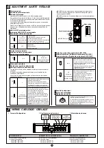
5
AREA MASKING SHEET
(1)
Cut the necessary area number on the area mask-
ing sheet.
See the area masking picture for your reference
and cut out the same place on both horizontal and
downward zones.
(2)
Attach the area masking sheet to the lens holder
located inside cover.
(3)
Attach cover and check detection zone.
*Zone
i
cannot be masked by area masking sheet.
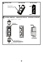
8
INSTALLATION
Before the installation
(1)
Read
2
PRECAUTIONS
before installation.
(2)
Loosen cover locking screw and detach cover.
(3)
Refer to
7
WIRING
and connect wires to the
terminal.
(4)
Install the unit.
(5)
Refer to
3
DETECTION AREA
and
OPERATION
CHECK
and check detection area and operation.
(6)
Replace the cover.
OPERATION CHECK
(1) Setting for operation check
∗
Operation LED: ON
|
Determine the required area of detection and
set the horizontal angle of the sensor and detec-
tion distance.
|
Attach cover and fix it to the sensor with the
locking screw.
|
Turn the power ON and wait for 1min.until the
alarm LED stops blinking.
|
After warm-up period, operate a walk test in the
detection area to check, if the required area is
covered.
|
Readjust sensitivity, masking or count if
necessary.
(2) Operation check
|
Make final setting according to the purpose.
|
Attach cover and check if operation LED and
connected devices operate properly.
∗
Make sure that there is no undesirable detection
of traffic including vehicles if there is a path or
road at the front of detection zone.

