


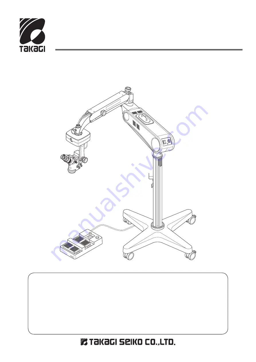
Operating Microscope
MODEL OM-8
Instruction Manual
IM(OM-8)E Rev.1
We would like to thank you for purchasing our Operating Microscope. Read
this manual thoroughly before use, understand the contents, and handle this
instrument safely and correctly
● Do not use this instrument in any other way than described in this manual.
● Keep this manual handy for future reference.
● Contact our distributor or our Sales Department if this manual is lost or
damaged.
OM8-T01


