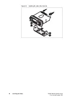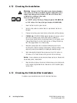
TM9300/TM9400 Installation Guide
Installing the Radio
35
© Tait Limited
December 2015
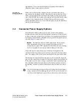
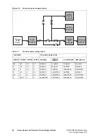
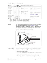
Shielding
If the auxiliary cable is longer than 4 feet (1m) it is recommended that the
cable and connector backshell are shielded.
shows the
recommended shielding arrangement. The earth braid wire (bare copper)
and aluminum foil should only be earthed at the radio end of the cable.
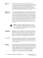
No Ignition Signal
If hardware link LK1M is fitted (factory default) and the ignition signal is
not used, the standby current is approximately 50mA. To reduce the
standby current to <3mA either:
■
remove hardware link LK1M, or
■
connect pin 4 (AUX GPI3) to pin 15 (AGND) of the auxiliary connector
Notice
The hardware links are SMT components. Do not replace
SMT components unless you are trained and equipped to do so.
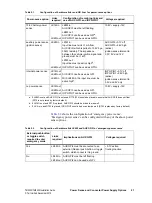
Table 4.3
Auxiliary connector - input levels
Parameter
Voltage
a
Test method and conditions
Comments
min.
max.
units
Input low level:
All inputs
AUX_GPI2
0.7
V
s
–4
V
V
No hardware links fitted
b
.
LK3M fitted.
Includes AUX_GPI3 with LK1M/2 fitted.
Configured as emergency power sense
input.
Input high level:
All inputs
AUX_GPI2
AUX_GPI3
1.7
V
s
–1.5
2.6
V
V
V
No hardware links fitted
.
LK3M fitted.
LK1M and/or 2 fitted.
Configured as emergency power sense
input.
Configured as power sense input (see
).
Safe DC input limits:
AUX_GPI1-3
AUX_GPIO4-7
AUX_RXD
AUX_TXD
c
–0.5
–0.5
–25V
–10
V
s
+0.5
V
s
+0.5
V
s
+0.5
V
s
+0.5
V
V
V
V
The input current must not exceed
±
50mA. This is the rating of the
clamping diodes.
a. The radio will tolerate a supply voltage range of 10.8V to 16.0V at the radio.
b. For more information on hardware links refer to Table 3.1 on page 21.
c. This output is protected against accidental input to the limits specified.
Figure 4.5
Auxiliary cable and connector shielding
metal D-range shroud in
contact with backshell
metal backshell
signal earth wire
aluminum foil
cable insulation
metal cable clamp
earth braid wire
analog ground pin

