TM9300/TM9400 Installation Guide
Installing the Radio
27
© Tait Limited
December 2015
Removing the
Control Head
Notice
During this procedure, take care that the control-head seal is
not damaged. Damage to this seal reduces environmental protection.
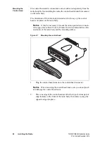
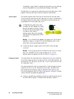
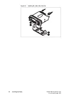
On the underside of the radio, two lever points are indicated on the radio
body by a dot-dash-dot pattern (
). The lever point is between the
control-head seal and the control head.
1.
At either of the lever points, insert a 3/16 inch (5 mm) flat-bladed
screwdriver between the control head and the control-head seal.
2.
Use the screwdriver to lift the control head off the snap feature, then
repeat in the other position. The control head can now be removed
from the radio body.
4.4
Selecting the Mounting Position
Requirements for
Safe and
Convenient
Installation
Ensure the mounting position complies with the following safety warnings:
Warning
Safe radio mounting!
■
Mount the radio securely so that it will not break loose in the
event of a collision. An unsecured radio is dangerous to the
vehicle occupants.
■
Mount the radio and the microphone where they will not
interfere with the deployment of airbags, the vehicle operator
controls, the vehicle operator’s view.
Caution
The bottom surface of the radio and the heatsink fins can
become hot during prolonged operation. When installing the radio,
position the radio so that it is not possible for the radio user to touch the
bottom surface of the radio and the heatsink fins.
Gap Between
Radio Body
and Mounting
Surface
Notice
It may be necessary to mount the radio upside down to main-
tain a gap of more than 3/8 inch (10 mm) between the bottom surface of
the radio body and the mounting surface.
Figure 4.2
Removing the control head
lever point
indication of
lever point
control-head
seal
control head

