D - 14 Reassembling the radio
09/01 IPN: M5000-00-102
Fitting the PCB to the chassis and
replacing the RF out assembly
Put the battery contact seal over the battery
contacts rather than into the chassis. If you put
the seal on the chassis, the contacts will squash
the seal.
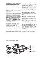
Fit the replacement RF out assembly as shown
in Figure D-11.
If you have removed the antenna connector or
either of the switches, fit them on the PCB
(refer to Figures D-8 and D-9), but do not yet
solder them in place. Align them with the holes
in the chassis, and as you lower the PCB onto
the chassis, make sure the accessory flex
protruding from the chassis fits into the socket
on the PCB. Lower the PCB onto the chassis,
making sure it is firmly seated.
Fit the PA screw loosely in place. Align the
switches so they are centred, referring to
Figures D-8 and D-9 for placement.
Figure D-12 shows the reassembly of the
antenna and switches. Replace the washers,
making sure the cone faces up. The nuts for the
two switches are black.
Replace the nuts, making sure they are thread-
ed correctly before using an 8 mm long reach
socket driver set to 10 inch pounds. Then tight-
en the PA screw to 2 inch pounds.
Using a heavy-tip soldering iron (e.g. Weller
2PTCC8 tip), solder the antenna connector
and two switches in place, if required, taking
care not to damage the surrounding compo-
nents.
Replace the knob seal over the antenna
connector and the two switches (see Figure
D-12).
Fitting the shield to the chassis
Replace the microphone grommet over the
microphone.
Replace the shield from the top of the radio,
ensuring that the two pins on the chassis go
into the two holes at the top of the shield.
Should the main seal need replacing, place the
new seal so that the notch at the top of the
chassis (behind the channel selector switch)
matches that on the seal and the profile match-
es the chassis.
Run your finger around the seal to ensure that
it fits properly into the seal retaining well.
Figure D-11: Placing the RF out assembly
2
4
3
1
RF out assembly
insert here
antenna connector
auxiliary flex socket
1
2
3
4


