background image

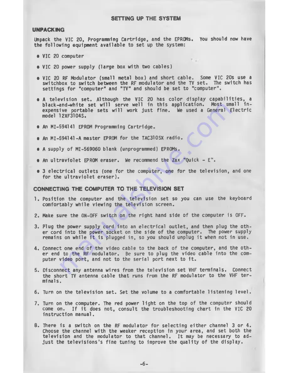
SETTING  UP  THE  SYSTEM

UNPACKING

Unpack  the  VIC  20,  Programming  Cartridge,  and  the  EPROMs.  You  should  now  have
the  following equipment available  to  set  up  the  system:

•  VIC  20 computer

•  VIC  20  power  supply  (large  box with  two  cables)

•  VIC  20  RF Modulator  (small  metal  box)  and  short  cable.  Some  VIC  20s  use  a 

switchbox  to  switch between  the  RF modulator and  the  TV  set.  The  switch  has 
settings  for  "computer"  and  "TV"  and  should  be  set  to  "computer".

•  A  television  set.  Although  the  VIC  20  has  color  display  capabilities,  a 

black-and-white  set  will  serve  well  In  this  application.  Most  small  In­
expensive  portable  sets  will  work  just  fine.  We  used  a  General  Electric 

model  12XF3104S.

•  An  MI-594141  EPROM Programming  Cartridge.

•  An MI-594141-A master  EPROM  for  the  TAC310SX  radio.

•  A supply  of MI-569060 blank  (unprogrammed)  EPROMs.

•  An  ultraviolet  EPROM eraser.  We  recommend  the  Zax  "Quick  -  E “.

•  3  electrical  outlets  (one  for  the  computer,  one  for  the  television,  and one 

for  the  ultraviolet eraser).

CONNECTING  THE  COMPUTER  TO  THE  TELEVISION  SET

1.  Position  the  computer  and  the  television  set  so  you  can  use  the  keyboard 

comfortably while  viewing  the  television  screen.

2.  Make  sure  the  ON-OFF switch on  the  right hand  side  of  the computer  is  OFF.

3.  Plug  the  power supply cord  Into  an  electrical  outlet,  and  then  plug  the  oth­

er cord  into  the  power  socket on  the  side of  the computer.  Ttie  power  supply 

remains  on while  It  Is  plugged  in,  so you  should unplug  It when not  In use.

4.  Connect one end  of  the  video cable  to  the  back  of  the  computer,  and  the oth­

er  end  to  the  RF  modulator.  Be  sure  to  plug  the  video  cable  Into  the  com­
puter  video  port,  and  not  to  the  serial  port next to  It.

5.  Disconnect any antenna wires  from  the  television  set  VHF terminals.  Connect 

the  short  TV antenna  cable  that  runs  from  the  RF modulator  to  the  VHF  ter- 

mi nals.

6.  TUrn on  the  television  set.  Set the  volume  to  a  comfortable  listening level.

7.  Turn  on  the computer.  The  red  power  light  on  the  top  of  the  computer  should 

come  on. 

If  it  does  not,  consult  the  troubleshooting  chart  In  the  VIC  20 

instruction manual.

8.  Ttiere  Is  a  switch  on  the  RF modulator  for  selecting  either  channel  3  or  4. 

Choose  the channel  with  the  weaker  reception  In your  area,  and  set  both  the 
television  and  the  modulator  to  that  channel.  It  may  be  necessary  to  ad­

just  the  televisions's  fine  tuning  to  improve  the  quality of  the  display.

-6 -

Содержание TAC 310SX

Страница 1: ...TAC 310SX A 14 or 16 channel synthesized VHF or UHF mobile radio small enough for dashmounting EPROM Programming Instructions Y j ov TACTEC SYSTEMS INCORPORATED...

Страница 2: ...nsertion force ZIF socket 1s not present in the equipment use an EPROM IC puller or a small bladed screwdriver to alter nately pry up one end then the other prying a small amount at a time PROPRIETARY...

Страница 3: ...omputer to theTelevision Set 6 To Avoid Confusion About theD i s p l a y 7 Plugging 1n the ProgrammingCartridge the First T i m e 7 Loading the Master EPROM 9 Main M e n u 9 Starting O v e r 10 Ttie F...

Страница 4: ...VIC 20 CONTROLS AND PORTS FUNCTION KEYS GAME PORT ON OFF POWER POWER SOCKET not u cf SWITCH LIGHT attach power supply her 4...

Страница 5: ...ERTION FORCE ZlF EPROM SOCKET BLOCK SELECT SWITCH set to BLOCK 5 at shown Use the switch numbers embossed on the case not the ones on the switches EDGE CONNECTOR plugs into computer Expansion Port CAU...

Страница 6: ...keyboard comfortably while viewing the television screen 2 Make sure the ON OFF switch on the right hand side of the computer is OFF 3 Plug the power supply cord Into an electrical outlet and then plu...

Страница 7: ...PLAY Please note 0 the letter 0 as in Open 0 ZERO 1 the letter I as in Input 1 the number ONE Cursor PLUGGING IN THE PROGRAMMING CARTRIDGE THE FIRST TIME 1 Pick up the programming cartridge If an EPRO...

Страница 8: ...switch has two functions a the PROG position enables the computer to operate with the programming cartridge b the MIMIC position enables you to jumper to an external computer If you flip the switch t...

Страница 9: ...set 3 Unlatch the EPROM socket by pulling up on the handle with the green knob REMEMBER Turn OFF the socket switch whenever you change EPROMs 4 Place the master EPROM Into the EPROM socket notched en...

Страница 10: ...making changes in the frequency list STARTING OVER RIJN You can always return to the main menu like this Press Tnp type RUN then press RETURN THE FREQUENCY LIST INITIALIZE If all of the frequencies a...

Страница 11: ...programmed EPROM in the ZIF socket notched end away from you Turn the SOCKET switch ON REMEMBER Turn OFF the socket switch whenever you change EPROMs Be sure the notched end of the EPROM faces away f...

Страница 12: ...channel number you wish to edit then press RETURN 3 The display then switches to the transmit edit menu as follows EDIT CHANNEL N TX FREQ MHZ FROM NNN NNNN TO 4 Type in the new channel frequency or N...

Страница 13: ...again using the correct information Continue editing until all channels have been properly listed When you have finished editing Press RETURN when the screen prompts EDIT CHANNEL The display will retu...

Страница 14: ...EPROM press function key fl The computer will return to step 4 above Pressing function key f3 will return the computer to the previous menu b If the EPROM is blank you may proceed with the programmin...

Страница 15: ...NN NNNN NNN NNNN 4 NNN NNNN NNN NNNN 5 NNN NNNN NNN NNNN 1 NNN NNNN NNN NNNN 2 NNN NNNN NNN NNNN 3 NNN NNNN NNN NNNN 4 NNN NNNN NNN NNNN 5 NNN NNNN NNN NNNN 1 NNN NNNN NNN NNNN 2 NNN NNNN NNN NNNN 3 N...

Страница 16: ...YPE PRIOR TO PROGRAMMING 2732 REQUIRES 25 VOLTS 2732 A REQUIRES 21 VOLTS PROM QUEEN VOLTAGE MUST BE SET PROPERLY OR PROM CAN BE DAMAGED UNIT MUST BE RE TUNED AFTER PROGRAMMED EPROM INSTALLED R E F E R...

Страница 17: ...ogrammer B Turn on the computer and the programmer C Lake certain that there is no EFBQf in the socket B Set Burn frog switch to 3urn E Adjust ueen I Adjust for the desired voltage F 3et Burn Prog swi...

Страница 18: ...h a V O M o f i m p e d a n c e o f 10 000 O h m s V o r g r e a t e r FLIP THE BURN PROG SWITCH BACK TO PROG BEFORE YOU OPERATE ANY OTHER SWITCHES AND WAIT UNTIL THE RED LED GOES OUT G 2732 2732A PRO...

Страница 19: ...TACTEC TAC TAC310 SX and Quiet Channel are trademarks of TACTEC Systems Inc TACTEC Systems Inc Meadow Lands Pennsylvania 15347 IB 8023351...

Отзывы: