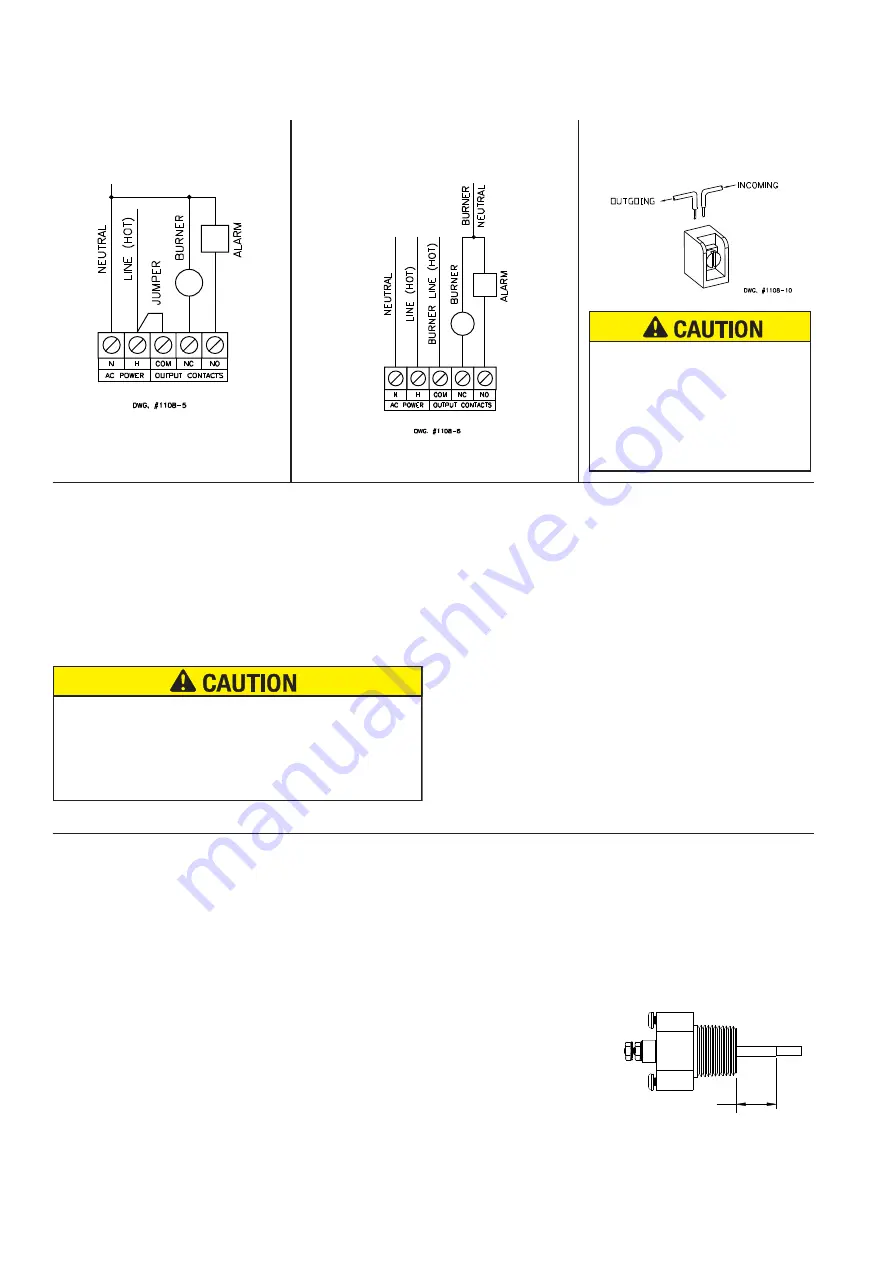
TERMINAL BLOCK CONNECTIONS
CLAMPING PLATE TERMINAL
FIG. 8
LWCO WIRING DIAGRAM USING
BURNER CIRCUIT POWER SOURCE
FIG. 6
LWCO WIRING DIAGRAM USING POWER
SOURCE OTHER THAN BURNER CIRCUIT
FIG. 7
*
*Factory Installed
Wire insulation must be rated at
167º F (75º C) or greater. Use at
least 18 AWG copper conductors,
or as required by code. Use of other
wire or insulation types could result
in fire causing property damage or
serious injury.
NOTE:
For 24 VAC LTA-2 models, LTA0243S-2, 24 VAC to be
supplied by an
EXTERNAL
Class 2 power source to terminals
H and N. For 120 VAC LTA-2 models, LTA1203S-2, 120 VAC is
supplied by an external circuit to terminals H and N.
LWCO Wiring Using the Burner Circuit Power Source
(See Fig. 6):
1. Connect the hot lead wire from the power source to terminal
H
.
2. Connect the neutral lead wire from the power source to terminal
N
.
3. Verify that factory installed jumper is present or connect an 18
AWG (min.) jumper wire from terminal
H
to terminal
COM
.
4. Connect the neutral wire of the power source to the neutral
side of the burner circuit. Connect wire from the hot side of the
burner circuit to terminal
NC
.
5. Connect the neutral wire of the power source to the neutral side
of a water feeder or alarm. Connect wire from the hot side of
the water feeder or alarm to terminal
NO
.
LWCO Wiring Using a Power Source Other than Burner
Circuit (See Fig. 7):
1.
Remove Factory installed jumper.
2. Connect the hot lead wire from the separate power source to
terminal
H
.
3. Connect the neutral lead wire from the separate power source
to terminal
N
.
4. Connect the hot lead wire from the burner circuit power source
to terminal
COM
.
5. Connect the neutral wire of the burner circuit power source to
the neutral side of the burner circuit. Connect wire from the hot
side of the burner circuit to terminal
NC
.
6. Connect the neutral wire of the burner circuit power source to
the neutral side of a water feeder or alarm. Connect wire from
the hot side of the water feeder or alarm to terminal
NO
.
Be sure the power source for Control Unit and burner circuit
are the same voltage. Make sure you are not introducing
a second voltage source into the burner circuit via the
jumper. This will bypass other operating limit, and/or safety
controls, which may result in property damage, personal
injury, or death.
Testing:
1. DO NOT fill boiler. Set thermostat to lowest possible setting
and turn on electric power to the boiler. On initial start-up, the
LTA-2 will indicate a low water condition, which indicates
proper function. The "STATUS" LED on the control unit should
illuminate RED. The burner should not operate without water
in the system.
2. Fill boiler with water. Once water covers the probe, the "STATUS"
LED on the control should turn from RED to GREEN.
3. Set thermostat to call for heat and verify that the burner ignites.
4. With the burner aflame, depress and hold the test switch while
observing the burner and the "STATUS" LED on the LTA-2. After
the "STATUS" LED illuminates RED, the burner should turn off.
5. Release the test switch and verify that the burner ignites
(provided water covers the probe). The "STATUS" LED on
the control unit should turn from RED to GREEN.
6. If burner fails to cutoff or relight, see the Troubleshooting section
for details. Otherwise, set the thermostat to its normal setting.
Once correct operation of the LTA-2 has been tested, test all other
safety, limit, and control devices before finalizing system operation.
PROBE CLEANING
FIG. 9
TEFLON SLEEVE INSULATOR
(Be careful not to damage during cleaning)
DWG #1108-8
Cleaning, Maintenance, and Replacement:
• Test the operation of the LTA-2 annually, or more frequently,
by pressing the “TEST” button. The “STATUS” LED should
turn RED and the boiler should shut down.
• Probe must be inspected every 5 years, (or sooner if “SERVICE”
LED turns on), for scale build-up or coating. Clean all oils, fluxes,
and scale from probe with a clean rag.
• The control unit should be replaced every 15 years. In areas
of high humidity, heavy dust, or other airborne contaminants
more frequent replacement may be required.


