background image

24

OPEraTiOn

iMPOrTanT! 

never start the saw without first checking the 

following: that the saw is secure; the saw table is assembled and 

adjusted; that blade tension is as required and that safety devices are 

checked. do not connect the saw to the mains before making sure that 

all of the above have been completed. Otherwise, the saw may start 

up accidentally and lead to serious injury.

1. sTarTinG UP anD sTOPPinG THE MaCHinE:

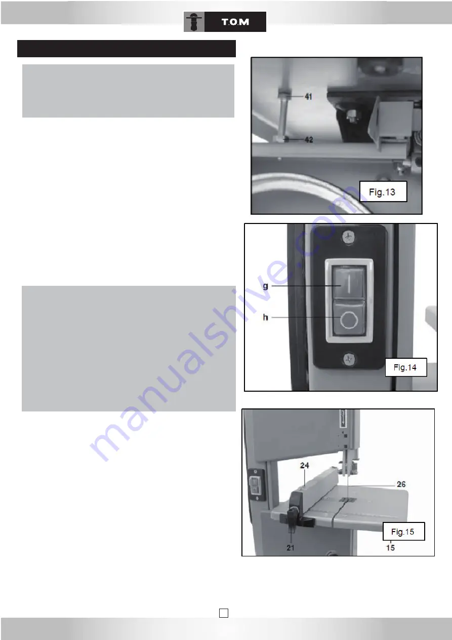
- to start up the machine, push the green button (g) fig.14. 

- to stop the machine, push the red button (h) fig.14.

the machine is equipped with a no-volt release switch.

this cuts off power to the machine if there is a voltage drop, if the 

power cord is too long, or if the power supply fails. If the machine 

stops, set the on/off switch (g) to "I" to switch it back on.

2. insTaLLinG THE riP fEnCE:

a. the rip cutting guide or rip fence (24) fig.15 may be fitted on the 

right or on the left of the blade (26). Slide it on to the table and adjust it 

as desired.

b. push the locking handle (21) downwards to lock the rip fence (24). If 

the rip fence is not sufficiently tightened, turn the handle (21) clockwise 

a few times until the rip fence is properly secured.

c. Make sure that the rip fence (24) is always parallel to the blade (26).

d. to unlock the rip fence (24), raise the locking handle (21).

assembly and adjustments

DanGEr

In order to minimise the risk of injury, please follow the safety instruc-

tions below when operating the saw:

- use personal protective equipment.

- Only cut one workpiece at a time

- while sawing, always press the workpiece against the table.

- do not jam the workpiece.

- do not slow down the saw blade by pressing it sideways.

- As required, use the following:

A push stick if the distance between the stop bar and the blade is 120 

mm or less;

A support surface for long workpieces, which might otherwise fall off 

the table after the cut has been made;

A dust extraction system;

while sawing round stock, use an appropriate retaining device to keep 

it from turning.

while sawing thin pieces on edge, an appropriate stop angle must be 

used to prevent them from falling over.

before starting work, make sure that the following are in perfect wor-

king order: 

- saw blade

- saw blade protection

Replace all damaged parts immediately.

Assume a correct working position while using the machine (the saw’s 

teeth must point towards the operator). 

never cut several workpieces at the same time. never bundle work-

pieces together to cut them. there is a risk of injury if individual pieces 

are caught in an uncontrolled manner by the saw blade.

never cut workpieces to which ropes, cords, strings, cables or wires 

are attached or which contain such materials.

OPEraTiOn

Содержание TR205A

Страница 1: ...SCIE A RUBAN DEUX VOLANTS BANDSAW BANDS GE Manuel d utilisation Operating instructions Bedienungsanleitung Tr205a...

Страница 2: ...2...

Страница 3: ...tor parts list 36 TSR 210 stand parts list 38 conformity and warranty 43 deutsch allgemeine sicherheitsregeln 23 zus tzliche sicherheitsregeln f r tischkreiss gen 24 Symbole 25 installation 25 spezifi...

Страница 4: ...1203 1996 07 Les valeurs cit es sont des valeurs d mission calcul es selon les normes en vigueur et non des valeurs li es l utilisation sur le lieu de tra vail Bien qu il y ait une corr lation entre c...

Страница 5: ...fait de transporter les outils lectriques avec un doigt sur l interrupteur ou de les bran cher lorsque l interrupteur est en position marche peut engendrer des accidents d Enlevez les cl s de r glage...

Страница 6: ...la pi ce contre la table et l avancer une vitesse mod r e 12 ARRETER la machine s il faut reculer la pi ce couper avant qu elle ne soit compl tement coup e 13 EFFECTUER des coupes en d brayage avant...

Страница 7: ...7 DESCRIPTION DE L APPAREIL...

Страница 8: ...le ruban de la scie 26 se trouve au centre de la table de sciage Replacez la but e de sortie du ruban 4 Introduisez l insert de table 17 Fig 5 de fa on ce que la fente soit dans la continuit de celle...

Страница 9: ...serrant la vis plastique 14 Fig 2 qui se situe sur la molette de r glage 22 Puis refermez les portes du carter 12 par les syst mes des fermetures 13 3 R glage du guide lame superieur Le guide lame sup...

Страница 10: ...en refermer les portes du carter Les deux portes du carter doivent tre ferm es losque la machine fonctionne Il est interdit de d marrer la machine si les portes sont ouvertes 5 R glage de la hauteur d...

Страница 11: ...r ne tombe 8 Raccordement de l aspiration des copeaux ATTENTION l inhalation de certains types de sciure par exemple de ch nes de h tre ou de fr ne peut provoquer un cancer ne travaillez dans des espa...

Страница 12: ...rientant vers le bas pour bloquer le guide parall le 24 Si le serrage du guide parall le n est pas suffisant tournez la poign e 21 de quelques tours dans le sens des aiguilles d une montre jusqu que l...

Страница 13: ...a ATTENTION Utilisez toujours un poussoir lorsque vous sciez des pi ces courtes Le poussoir 28 Fig 16 doit toujours tre port e de main et fix son crochet 29 pr vu cet effet MAINTENANCE ET ENTRETIEN AT...

Страница 14: ...poussi re etc Apr s chaque travail d entretien ou de nettoyage contr lez le bon fonctionnement de tous les dispositifs de s curit Ne pas remplacer les pi ces endommag es en particulier les dispositif...

Страница 15: ...idement la scie sur un sol appropri Table de sciage l che Positionnez la table de sciage et fixez l Fixation du moteur l che Contr lez les vis de fixation et resserrez les en cas de besoin Manchon d a...

Страница 16: ...10 motor parts list 36 TSR 210 stand parts list 38 conformity and warranty 43 deutsch allgemeine sicherheitsregeln 23 zus tzliche sicherheitsregeln f r tischkreiss gen 24 Symbole 25 installation 25 sp...

Страница 17: ...alculated according to applicable standards and not values relating to use in the workplace Although correlation between those different emission levels does exist this cannot be reliably used to dete...

Страница 18: ...a finger on the switch or connecting them with the switch set to on can lead to injuries d Remove any adjustment keys or wrenches before starting up the power If a key or wrench remains attached to a...

Страница 19: ...EVER draw out cutting lines assemble or prepare a task on the saw table when the saw is running 17 ALWAYS hold the workpiece firmly against the table 18 AVOID awkward positions where your hands risk c...

Страница 20: ...tment knob 10 Upper blade guard 11 Upper blade guide 12 Housing door 13 Closing the housing door 14 Locking the saw blade upper wheel 15 Saw table 16 Bevel scale 17 Table insert 18 Bevel locking handl...

Страница 21: ...ct the blade tension if required Turn the blade tension adjustment knob 9 Fig 1 clockwise to tighten the blade Turn the blade tension adjustment knob 9 Fig 1 anti clockwise to slac ken the blade 2 ADJ...

Страница 22: ...y The support bearing and the guide bearings must be readjusted with every blade change and blade readjustment Note Regularly check the guide bearings for wear and replace both of them at the same tim...

Страница 23: ...rew 41 7 TILTING THE SAW TABLE Fig 14 The saw table can be tilted up to 45 for bevel cuts To tilt the table proceed as follows a Loosen the table tilt locking handle 18 Fig 2 b Pivot the table to the...

Страница 24: ...26 d To unlock the rip fence 24 raise the locking handle 21 Assembly and adjustments DANGER In order to minimise the risk of injury please follow the safety instruc tions below when operating the saw...

Страница 25: ...rubber tyres 3 of the two wheels 7 and 8 h Turn the blade tension adjustment knob 9 clockwise to tighten the blade i Close the two saw doors 12 once more j Replace the blade stop 4 Then readjust the...

Страница 26: ...ed and approved by the manufacturer may cause unforeseen damage Maintenance and repair work other than as described in this chapter must only be carried out by qualified specialists 5 STORING THE SAW...

Страница 27: ...on to a suitable floor Saw table loose Position and fasten the table Motor mount loose Check the fastening screws and tighten them if necessary Extraction port blocked No extraction system connected...

Страница 28: ...arts list 36 TSR 210 stand parts list 38 conformity and warranty 43 deutsch allgemeine sicherheitsregeln 23 zus tzliche sicherheitsregeln f r tischkreiss gen 24 Symbole 25 installation 25 spezifikatio...

Страница 29: ...n geltenden Normen berechnete Emissionspegel und nicht um mit der Verwendung der Maschine am Arbeitsplatz in Zusammenhang stehende Werte Zwar stehen Emissionspegel und L rmbelastung im Zusam menhang j...

Страница 30: ...as Tragen von Elektrowerkzeugen mit einem Finger auf dem Schalter oder das Anschlie en bei eingeschaltetem Ger t kann Unf lle verursachen d Vor dem Einschalten des Elektrowerkzeugs Einstellschl ssel a...

Страница 31: ...tisch Arbeiten wie das Anrei en von Schnittlinien Zusammensetzen von Werkst cken usw vornehmen 17 Das zu s gende Werkst ck STETS fest gegen den S getisch gedr ckt halten 18 Ung nstige Haltungen VERMEI...

Страница 32: ...re S gebandf hrung 12 Geh uset r 13 Verschluss der Geh uset ren 14 Arretierung der oberen S gebandrolle 15 S getisch 16 Neigungsanzeige des S getischs 17 Tischeinlage 18 Neigungsarretierung des S geti...

Страница 33: ...der Spannung des S gebands 26 Abb 2 mit dem Finger in der Mitte zwischen dem S getisch und der oberen S gebandabdeckung 11 Abb 1 seitlich gegen das S geband dr cken das S geband darf sich nur um 1 2...

Страница 34: ...e Bands genrolle 8 einige Male per Hand im Uhrzeigersinn drehen damit sich die F hrungsrollen in die richtige Position setzen beide F hrungsrollen sollen leicht am S geband anliegen 4 AUSRICHTEN DER U...

Страница 35: ...itig die S gebandf hrung 11 Abb 1 bis auf 2 3 mm ber dem Werkst ck absenken c Anschlie end den Arretiergriff 20 wieder anziehen ACHTUNG Vor dem Verstellen der oberen S gebandf hrung die Mas chine absc...

Страница 36: ...S ge sind zwingend folgende Schritte auszuf hren Befestigung der S ge Montage und Einstellung des S getischs Kontrolle der S gebandspannung berpr fung der Sicherheitsvorrichtungen Die S ge erst nach D...

Страница 37: ...richtige Arbeitsstellung einnehmen die S gez hne m ssen in Richtung Bediener zeigen Keinesfalls mehrere Werkst cke gleichzeitig s gen Keinesfalls zu einem B ndel zusammengefasste Einzelst cke s gen E...

Страница 38: ...ech 4 abnehmen d Zum Lockern des S gebands das Einstellrad 9 gegen den Uhrzeigersinn drehen e S geband 26 von der unteren 7 und der oberen 8 S gebandrolle abnehmen und durch folgende Maschinenelemente...

Страница 39: ...rheitsvorrichtungen ausschlie lich durch Original Ersatzteile ersetzen Vom Hersteller nicht zugelassene und berpr fte Ersatzteile k nnen unvorhersehbare Sch den verursachen S mtliche Wartungs und Repa...

Страница 40: ...estigung S ge ordentlich auf geeignetem Untergrund befestigen S getisch lose S getisch ausrichten und befestigen Motorbefestigung lose Befestigungsschrauben berpr fen und ggf festziehen Sp neabsaugstu...

Страница 41: ...41 vue clat e...

Страница 42: ...42 42 r f rences des pi ces...

Страница 43: ...dehors de nos r parateurs agr s En aucun cas durant la p riode de garan tie le mat riel ne devra tre d mont 1 Scope of the warranty The warranty shall only apply to manufac turing defects or material...

Отзывы: