4
5. Installation
Do not use excessive force that can cause damage when tightening threaded unions.
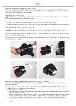
The numbers and other information cited below in parentheses are based on this illustration.
5.1.
Mounting
-
Install the UV-C radiator on th
e filter container’s cover and use the two screws (13/14) to attach it to the
mounting holes (34) provided.
-
Install the 2
“ outside thread connection (2
4) with the locking nut (20) and the seal (22).
-
Install the 32 mm connection (38) with the locking nut (37) and the seal (36) on the UV-C inlet (24).
-
Install the 1 ¼
“ outside thread connection (23) with the locking nut
(20) and the seal (22).
-
Install the 1 ¼
“ connecting
bend (35) on the 1 ¼
“ outside thread connection (23) with the outlet pointing
downwards.
-
Guide the outlet pipe (15) through the opening and fit this to the connecting bend (35).
-
Check that all locking nuts are tight and re-tighten once again if required.
-
Fit the three discharge taps (8) to the corresponding chamber. Guide the 1” threaded piece (9) with fitted
seal (10) from inside the chamber to outside. Screw the corresponding tap tight.
-
Fit the filter outlet (7) with the locking nut and the sealing ring to the point provided.
-
Insert the filter brushes (4) into the compartment provided.
-
Insert the filter sponges (5) into the compartment provided.
-
Insert the biological filter granulate (6) into the corresponding bag and together into the compartment
provided.
-
Place the cover with the fitted UV-C radiator onto the filter container and press it shut gently. The cover
(2) should latch onto the filter container (1) gently.
-
Filter inlet: Connect the pump (16) with the hose adapter (44) and a suitable hose to the inlet on the UV-C
radiator (38). Use a clip to secure the connection if required.
-
Filter outlet: Either connect the filter outlet with a suitable hose (50 mm) or with a rigid pipe. Ensure that
the filter and the UV-C radiator are a sufficient safety distance from the pond.
-
Switch the pump on, check whether the filter fills (lift the cover slightly) and whether the water flows out of
the filter outlet after a short delay.
-
Switch on the UV-C sterilizer and check that the lamp is working through the opaque glass screen.
Warning
-
T
he filter must always be positioned above the pond’s water level.
-
Place the filter horizontally (to prevent water overflowing).
-
To encourage water to leave the filter, the outlet pipe must never be higher than the level of the
connection hole it comes from.
-
In the event of an overflow, check whether the filter has been set up correctly in the horizontal position
and that the outlet is free. Your filter system is now ready for operation.
5.2.
Setting up at the garden pond
Place the filter above the water level (filter outflow at least 15 cm and no more than 2.5 m above the water
surface) and ensure that the filter is at least 2 metres away from your pond. The container should be placed
horizontally on a solid substrate (stone slab). Ensure, that it cannot fall into the water and that the installation
area of the filter cannot be flooded.
It is best to set up the filter where it is in the shade. If the interior of your filter should become very hot, then
its capacity is reduced.
To ensure safe operation, we recommend that you fix the hose ends in place on the hose connection pieces
with off-the-shelf hose clamps.
Always use the shortest possible hose length and avoid kinking the hose
For biological reasons, the immersion depth of the pond pump should be approx. 40 cm for optimal function
of the filter system. Ensure that the pond pump is placed on a silt-free substrate (stone slab).
5.3.
Placing in service
Attention! Comply with the safety measures specified for the UVC emitter and the pump (see above)!
(See the provided operating instructions).
Install the connection socket outlet in the water-protected area and at least 2 m away from the edge
of the pond!
13
Содержание MTS 30000 UV 24 INOX
Страница 49: ...1RWL HQ QRWHV QRWH QRWDV...
Страница 50: ...1RWL HQ QRWHV QRWH QRWDV...
Страница 51: ...1RWL HQ QRWHV QRWH QRWDV...


