4
7.3.
Overload protection
The built-in thermal overload trip prevents the pump from being overheated.
The pump must cool down.
Check the following operating conditions:
•
- Is there a sufficient water supply?
•
- Has the filter become clogged?
•
- Has dirt entered the pump housing (Follow the cleaning instructions below)?
•
- Have hoses or jets become clogged?
•
- Has the pump cooled down?
As soon as you have solved the problems, you can start the pump again, pulling the plug out and putting it
again in the socket after a short time (1 min.)
8. Dismounting / mounting the pump
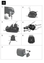
Figure III
1. Follow the safety measures.
Disconnect the pump
!
2. Remove the top shell from the pump cage in accordance with fig. III/1
3. Loosen the pump's retaining bracket as shown in fig.III/2
4. Remove the entire pump with pump housing from the lower shell. (III/3)
5. Unscrew the flow rate regulator from the inflow cover
6. Loosen the 4 screws (III/5).
7. Unclip pump housing (18) from motor housing (III/6).
8. Remove rotor assembly (19) from motor housing. Pay attention to the O-ring (22) in the motor housing (III/7).
9. Clean all parts using clear water and soft sponge.
Mounting:
10. Press the O-ring (22) onto the rim in the motor housing.
11. Push the rotor assembly (19) onto the motor housing (5) with precaution and turn the bearing cap so that the two
holes fit on the pins in the motor housing (5).
12. Make sure the rotor assembly is free and will turn.
13. Check the position of the O-ring (22) in the motor housing (5).
14. Plug the pump housing (18) in the motor housing (5) and tighten the 4 screws uniformly.
15. Re-insert the pump into the pump cage by following the steps in reverse order..
For trouble-free operation, repeat this procedure depending on the degree of fouling and duration of operation.
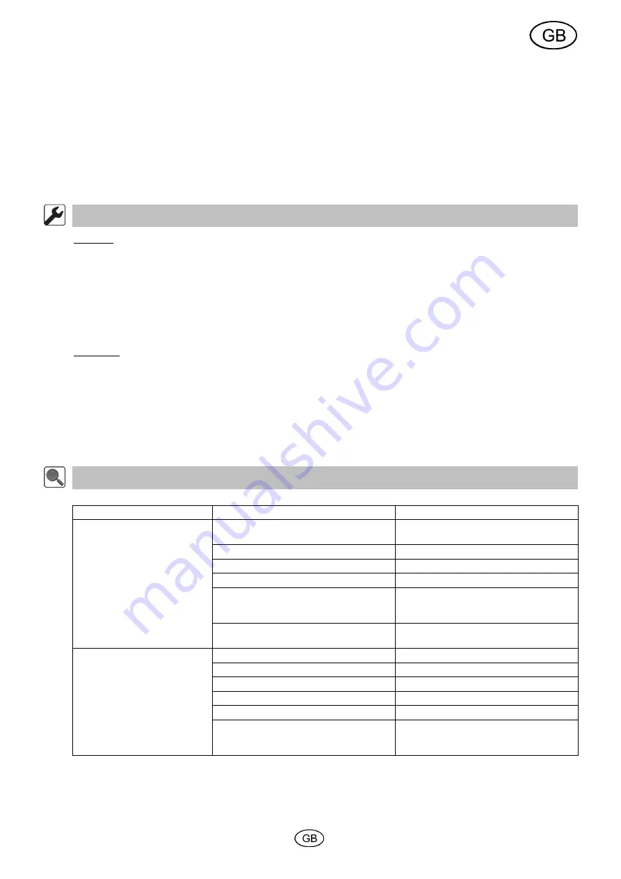
9. Troubleshooting/recommendations
Fault
Possible cause
Remedy
No delivery capacity
Power supply interrupted
Plug in the power plug
Check fuse
Cable is defective
Dispose of pump
Motor block is defective
Dispose of pump
Pump is calcified, rotor has seized
Dismantle pump and descale
Rotor is blocked by sand
Dismantle and clean pump
Change the set up location as specified in
the usage instructions
Pump is taking in air
Pump is too close to the water surface and
is taking in air
find a deeper location
Insufficient pump capacity
Front cover is clogged
Clean front cover
Hose system dirty
Clean hose and/or outflow
Hose is too long
Shorten the hose
Insufficient hose diameter
Use a hose with a larger diameter
Outflow is positioned too high
Reduce required delivery head
Pump is taking in air
Pump is too close to the water surface and
is taking in some air
find a deeper
location
9
Содержание BPF 8000 E
Страница 3: ...1 3 2 I 3 2...
Страница 4: ...II 5 2 1 3 4 6 7 8...
Страница 5: ...III 2 1 3 4 5 6 7...
Страница 6: ...IV...
Страница 47: ...1 T I P 1 1 2 2 3 2 4 2 5 3 6 3 7 3 8 4 9 4 10 5 11 5 12 5 1 8 RCD FI 30 mA 41...
Страница 49: ...3 5 10 m 2 25 mm 32 mm 40mm 6 IV 35 C I I 1 I 2 BPF 8000 E I 2 25 cm 2 m II 40 C 4 7 8 7 1 7 2 43...
Страница 51: ...5 10 vis major a 1 2 3 11 www tip pumpen de 12 PDF service tip pumpen de EU EU 2012 19 EK 45...


