background image

19

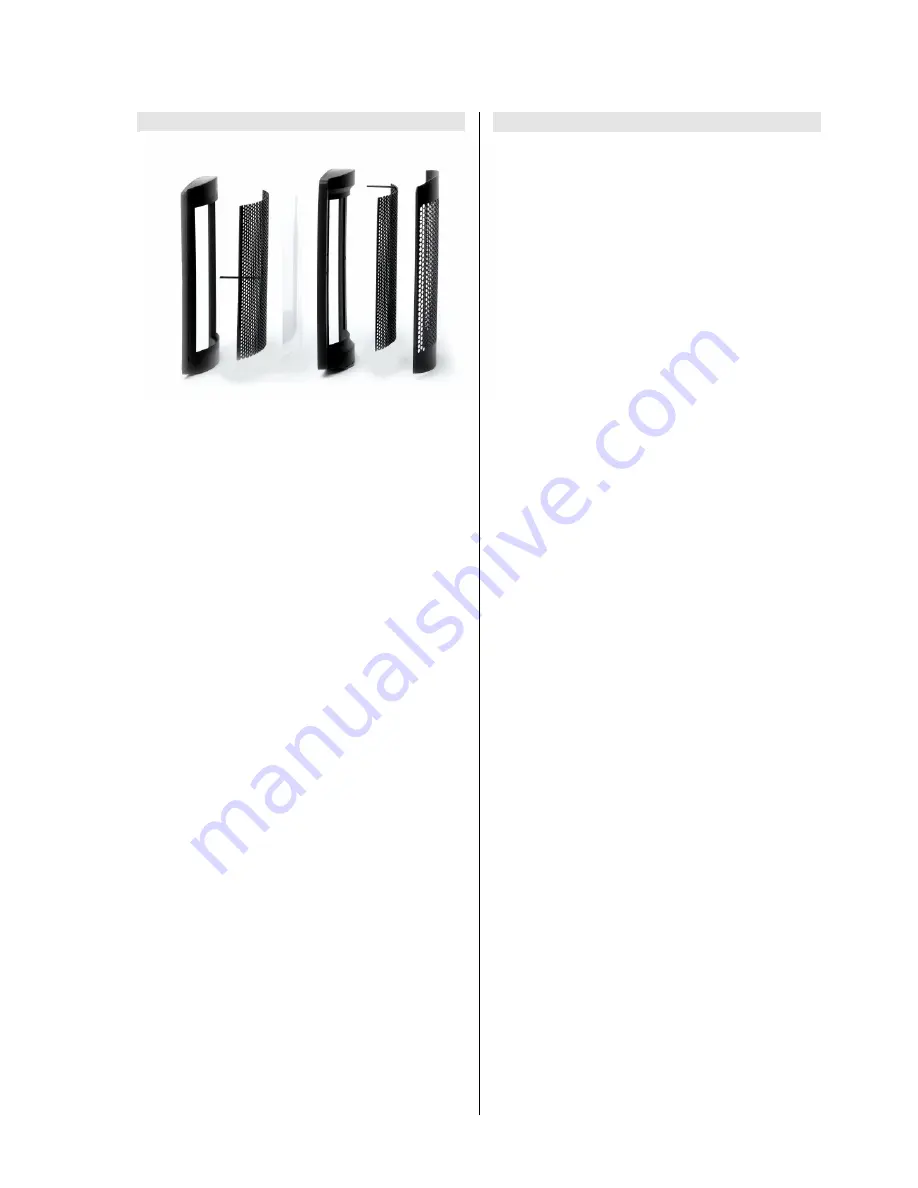
The electrostatic treble unit

Electrostatic  units  are  amongst  the  oldest  loudspeaker
technologies.  In  its  basic  form  a  featherlight  membrane
(in our electrostatic units only a few µm thick) is charged
electrically  and  held  between  two  electrodes,  to  which
the music signal is fed at a high voltage.

The foil is driven homogeneously over its entire surface,
and  for  this  reason  is  free  of  any  tendency  towards
partial  vibration.  With  its  low  mass  the  foil  is  practically
inertia-free,  endowing  the  electrostatic  device  with  a
virtually  perfect  transient  response.  The  extremely  high
upper  limit  frequency  (>  70,000  Hz)  of  these  systems  is
almost  beyond  the  reach  of  conventional  dynamic
loudspeaker systems.

These  are  the  reasons  why 

  has  developed  an

electrostatic treble unit, which is built using sophisticated
precision  tooling.  In  this  speaker  the  potential
advantages  of  all  electrostatic  drivers  -  superb  dynamic
characteristics,  transparency,  lightness  and  luminosity  -
are brought fully to fruition.

The  curvature  of  the  foil  membrane  produces  a  linear
frequency  response  even  under  large  off-axis  listening
angles of up to +/- 30°.

Electrostatic drivers require a power supply to charge up
the foil membrane, and that is why the 

TCI C2

 features a

mains  power  input.  In  the 

TCI C2

  the  amplifier  signal  is

driven to high voltage using a repeater.

The cross-over unit

A  very  sophisticated,  low-loss  passive  FSR  cross-over
unit  (FSR  = 

F

ast 

S

ignal 

R

esponse)  adjusts  the

combination  of  electrostatic  unit  and  repeater  (

TCI C2

),

to  match  the  output  of  the  other  sub-systems  in  the
loudspeaker.

The  circuit  boards  of  these  cross-over  units  feature  a
large-area  copper  layer  on  the  top  surface  whose  sole
purpose is to act as the earth conductor.

The  copper  tracks  on  the  underside  connect  the
components with each other. This layout ensures that the
critical  earth  reference  potential  is  not  falsified  by  the
large  signal  currents  which  flow.  The  usual  voltage
losses  caused  by  narrow  conductor  tracks  do  not  occur
in  this  design,  which  means  that  much  higher  currents
can safely be used. Undesired effects on signals such as
inter-modulation  or  cross-talk  between  the  individual
tracks are also minimised.

The  components  of  the  cross-over  unit  are  extremely
low-resistance  types,  and  are  designed  to  minimise
losses.

The  large  capacitance  required  is  implemented  in  the
form of several small capacitors wired in parallel, as this
arrangement  reduces  series  inductivity  and  resistance,
and  also  improves  slew  rates.  All  these  design  features
are aimed at obtaining maximum possible signal fidelity.

To  reduce  the  distortion  which  can  arise  with  large
currents, virtually all the coils are of the air-core type.

High-quality 

 cable is employed for all internal wiring

inside the cabinets.

Содержание TCI S 3

Страница 1: ...Bestell Nummer Order No 9103 0322 TCI C2 TCI S3 BETRIEBSANLEITUNG USER MANUAL TCI C 2 TCI S 3...

Страница 2: ...2...

Страница 3: ...3 Deutsch Seite 4 English page 15 Anhang Appendix Technische Daten Seite 27 Technical specifications page 27...

Страница 4: ...verhalten allen anderen berlegen nochmals liniearisiert und im Tiefstbass erweitert F r den Mitteltonbereich wurde ein v llig neues Chassis entwickelt das nicht nur ber eine unglaubliche Impuls wieder...

Страница 5: ...n einer High End Surroundanlage Mit diesem kompro misslos innovativen Lautsprecher erf llen wir aller h chste Anspr che TCI S3 Der TCI S3 ist ein weiteres innovatives Mitglied der TCI Familie Er ist e...

Страница 6: ...einem riesigen 120 mm Magnetsystem und einer 40 mm Schwing spule mit vierlagiger Titanschwingspule besteht ist in einem resonanzarmen Magnesiumguss Korb aufge h ngt Zusammen mit dem exakt berechneten...

Страница 7: ...ersignal wird bei der TCI C2 mit Hilfe eines bertragers hochgespannt Die Frequenzweiche Eine verlustarme sehr aufw ndige passive FSR Frequenzweiche FSR Fast Signal Response passt die Einheiten aus Ele...

Страница 8: ...ie Lautsprecher zus tzlich gegen Um fallen Zur Montage der Spikes oder M belgleiter legen Sie das Lautsprechergeh use an der Aufstellposition vorsichtig auf die Seite Schrauben Sie die vier Spikes gem...

Страница 9: ...wir laststabile Endstufen mit hoher Stromlieferf higkeit 7 Ampere f r TCI S3 10 Ampere f r TCI C2 Der D mpfungsfaktor der Endstufen sollte einen Wert von 400 haben als Ausgangsleistung sollten mindest...

Страница 10: ...gergebnis In der mittleren Schalter stellung arbeitet die TCI S3 wie eine normale 2 Weg Box Wir empfehlen die beste Schalterstellung durch H ren heraus zu finden Pegelanpassung TCI C2 Die Standlautspr...

Страница 11: ...11...

Страница 12: ...Auf den Netzstecker darf keine berm ige Krafteinwirkung ausge bt werden Durch die L ftungsschlitze d rfen keine Fl ssigkeiten oder Fremdk rper in das Ger t gelangen Im Inneren f hrt das Ger t Netzspa...

Страница 13: ...aser Dieses Material wurde auf Schadstoffe gepr ft nach ko Tex Standard 100 Dieser Test findet Anwendung f r Bekleidung Decken und Polster Matratzen Haus textilien usw Das von uns verwendete Vlies hat...

Страница 14: ...ustauschen St rung Flaches Klangbild zu wenig Bass wiedergabe Ursache Die Lautsprecherleitungen sind verpolt angeschlossen Abhilfe Den Anschluss der Lautsprecherleitungen an Boxen und Lautsprecherklem...

Страница 15: ...15 English...

Страница 16: ...ll others and in these speakers the linearity of the system has been further improved and the extreme bass response expanded still further For the mid range spectrum we have developed a completely new...

Страница 17: ...important speaker in any high end surround system With this innovative no compromise loudspeaker we have satisfied the most demanding of all requirements in this area TCI S3 The TCI S2 constitutes yet...

Страница 18: ...revious driver The gigantic 120 mm magnet system and a 40 mm voice coil consisting of four layers of titanium form an impressively powerful combination and are mounted in a low resonance cast magnesiu...

Страница 19: ...lifier signal is driven to high voltage using a repeater The cross over unit A very sophisticated low loss passive FSR cross over unit FSR Fast Signal Response adjusts the combination of electrostatic...

Страница 20: ...ldren do not usually play or provide some means of ensuring that the speakers cannot topple over To fit the spikes or furniture glides place the loudspeaker at its final location and carefully lay the...

Страница 21: ...mmend power amplifiers which are stable under load when supplying high currents i e 7 Amps for TCI S3 10 Amps for TCI C2 The damping factor of the power amplifiers should be rated as 400 we recommend...

Страница 22: ...CI S3 operates as a normal 2 way speaker We recommend that you carry out experiments to establish which switch position you prefer Level adjustment TCI C2 The floor standing loudspeakers of the TCI lo...

Страница 23: ...23...

Страница 24: ...o not exert undue force on the mains connectors Liquid or foreign bodies must never be allowed to get through the ventilation slots and inside the cabinet Mains voltage is present inside the unit and...

Страница 25: ...of 100 polyester fibres in conjunction with a binding fibre This material has been tested for harmful ingredients to Eco Tex Standard 100 the same test is used for clothing bedclothes pillows mattres...

Страница 26: ...sure to replace damaged cables Problem Flat sound image insufficient bass response Cause The loudspeaker cables are connected with reversed polarity Remedy Check the speaker connections at the loudspe...

Страница 27: ...ss drive unit 2 x 180 mm 1 x 180 mm TMT Best ckung Mittelton Mid range drive unit 1 x 180 mm Best ckung Hochton High freq drive unit Elektrostat Electrostatic 2 x 35 mm Frequenzweiche Typ Crossover un...

Страница 28: ...elektroakustik GmbH Co KG Herford Deutschland Germany...

Отзывы: