SYStronics TIC-4M Скачать руководство пользователя страница 2

TIC-4M MANUAL

2

Be sure to read and ensure that your safety precautions are used to protect your safety and prevent property 
damage. We shall not accept any liability for any loss caused by the use or carelessness caused by the use 
or handling of this manual.

Warning

If this product is not intended as a safety device, use a double safety device for fear of accidents, damage of 
critical peripheral equipment, and equipment that is feared to cause extensive property damage.

Safety instructions

1. Be sure to check the equipment after disconnecting mains.
2. Do not disassemble and repair this product ; it is not possible to manufacture any product.
3. Do not spray water directly or clean it with benzene, jazzy, or alcohol.

Notes on the Environment

Do not install this product in the following locations and environments :

1. Places directly exposed to mechanical vibration or shock
2. Places exposed to corrosive gases or combustible gases
3. Position directly exposed directly to direct sunlight
4. Places affected by electromagnetic waves
5. Places where high temperature or humidity is high (sites with over 85 % of ambient humidity)
6. Places where dust and salt are plentiful

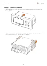
Precautions on installation

1. Make sure that the installation work is related to the installation or qualified personnel only.
2. Do not place any device or wiring that caused noise (NOISE) near the product.
3. Avoid near heating apparatus.
4. Disconnect all appliances (OFF) after disconnecting them from the wiring.
5. Do not work with wet hands. Risk of electric shock.
6. Install and use the method described in the User Manual as instructed in the Instructions for Use.
7. Do not turn on (power on) prior to the connection between the unit of manufacture of this unit.
8. Do not use any load exceeding the opening and closing capacity of the output contacts.

Immunity condition

1. In addition to the contents set forth herein, no warranties and responsibilities shall be made regarding this 

product.

2. Whether or not this product is likely to be unforeseen defects and natural disasters due to the use of this 

product, the user or the third person We shall not be held liable for any indirect damage.

Precautions

Содержание TIC-4M

Страница 1: ...301 Bucheon Techno park 345 Seokcheon ro Bucheon si Gyeonggi do Republic of Korea Phone 10 32 324 2777 Fax 10 32 324 2717 Homepage www ss22 com TIC 4M USER MANUAL Compact Temperature Controller VER 1...

Страница 2: ...nlight 4 Places affected by electromagnetic waves 5 Places where high temperature or humidity is high sites with over 85 of ambient humidity 6 Places where dust and salt are plentiful Precautions on i...

Страница 3: ...o input 2 ports by setting the temperature monitoring port according to the setting conditions and customize it to suit the site conditions This is a product that is equipped with a built in communica...

Страница 4: ...ent Controller 1EA TIC 4M Bracket 2EA Normal type NTC sensor 1EA SCTS 01 Sensor Component Advanced NTC sensor 1EA SCTS 02 High temperature type NTC sensor 1EA SCTS 03 Well type NTC sensor 1EA SCTS 04...

Страница 5: ...A Relay output Output Port 4 Port Input power output Input Port 2 Port Non power source Changeable to temperature sensor input Sensor Port 1 Port NTC 10K at 25 1 Communication Port 1 Port RS 485 Opera...

Страница 6: ...Advanced type cable sensor SCTS 02 Temperature Range 45 105 NTC 10K at 25 0 5 Sensor Weight 37 5g Cable 3M standard High temperature type cable sensor SCTS 03 Temperature Range 45 150 NTC 10K at 25 1...

Страница 7: ...TIC 4M MANUAL 7 Front view Product Dimension Top view Side view Front view Side view Bracket Dimension Controller Dimension Display 42 5 x 20 3...

Страница 8: ...mm x 30 mm in accordance with the specification insert the controller into the perforated holes 2 Push the controller onto the wall and secure it firmly by pushing the bracket When disconnecting remov...

Страница 9: ...duct Wiring Diagram L L Sensor INPUT COM DI1 DI2 DO1 DO2 DO3 DO4 220VAC Relay 220VAC 5A COMP FAN DEF AL circuit breaker R N 220VAC Set output function DO3 DO4 Input function input contact setting poss...

Страница 10: ...up screen Alarm generated for 2 seconds by pressing for 2 seconds DEF UP key Defrost ON OFF Detailed menu movement and increased menu data value PWR DOWN key Controller power ON OFF Detailed menu move...

Страница 11: ...t the current temperature of 20 or below Heating Deviation OFF 0 1 9 9 OFF The function of setting up the heater while operating the controller while operating the controller OFF Without auxiliary hea...

Страница 12: ...eter Set Main Display Cooling Delay After Defrosting Fan Delay after Defrosting Defrosting Time Defrost Cycle Defrost Mode Defrost Set High Temp Alarm Heater Alarm Comp Alarm Alarm Set Comp Integratio...

Страница 13: ...e Comp output is turned ON and OFF Fan Mode ON Au ON Set the air flow mode ON The fan output is ON whenever the controller is in operation Auto flower is driven in conjunction with the Compton output...

Страница 14: ...rature an alarm is generated If the temperature is 1 degree below the set point of the high temperature alarm the alarm is cleared Heater operation stops when high temperature alarm occurs OFF Alarm i...

Страница 15: ...een Input Contact 1 Input 2 Set Input 1 Set Output 4 Set Output 3 Set System Set Comp Alarm Return Alarm Set Temp Filtering Temp Display Interval Display Set Input Contact 2 Temp Sensor Calibration Lo...

Страница 16: ...ct method of the port n o Operates normally when the corresponding input is detected n C Normal operation should be performed if no corresponding input is detected during operation Alarm Setting Categ...

Страница 17: ...of the operation alarm Normal operation High Temp Alarm Alarm occurs when control temperature is higher than high temperature alarm during controller operation Heating operation stops when an alarm oc...

Страница 18: ...Reset Push for more the 2sec Notice All settings on the controller will return to their initial state Push for more the 10sec Main Screen Factory Reset Menu Factory Reset Complete Factory Reset Cance...

Страница 19: ...he precautions and instructions specified in the manual For more information on the service refer to the product warranty statement in the user manual 1 Please note that any problem failure caused by...

Страница 20: ...o generate noise 4 Noise source may occur due to contact switching Among the causes of the above noise sources the noise that the system manufacturer can reduce is only the contact switching noise Con...

Страница 21: ...to install close to the line where the noise is generated and the line where the noise is generated by placing a plated steel barrier 2 If you need a lot of noisy power in area A it is recommended to...

Страница 22: ...il s positive or negative terminal or an equivalent snubber capacitor Generally 100 and 0 1Uf are connected in series but it needs to be adjusted according to the load power How to Identify the Source...

Страница 23: ...TIC 4M MANUAL 23...

Отзывы: