background image

6

Installation

5.1

Where/how to install

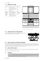
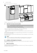
Fig. 3 SAVE VTR 150/K in a kitchen environment

The SAVE VTR 150/K is to be mounted above a stove.

A

Minimum distance
between cabinets (mm)

600

B

SAVE VTR 150/K unit
width (mm)

598

C,
Electrical
stove

Minimum distance
between stove surface
and cooker hood (mm)

450
(Recommen-
ded 500)

C, Gas
stove

Minimum distance
between stove surface
and cooker hood (mm)

650

5.2

Wall preparation for mounting bracket

The unit should be installed in such a way that there is no vibration noise
coming from the wall on which the unit is installed.

5.3

Outdoor Air Intake Location Recommendation

Recommended installation location for the outdoor air intake is the northern or eastern side of the building and with a
distance to openings for discharge of stale ventilation air, kitchen ventilator, central vacuum system, waste water drain-
age and other pollution sources like exhaust from traffic, etc. Exhaust air should ideally be led via a roof cowl to the out-
side and with a good distance from the outdoor air intake, windows, etc.

5.4

Access to Power supply

The SAVE VTR 150/K is supplied with approximately 1,5 m cable and plug for 230V, single phase earthed connection.

Make sure a power outlet is reachable by the plug.

6

Installation

Important

The device may only be installed by qualified, instructed and trained personnel. The persons must know the
relevant safety directives in order to recognise and to avoid risks.

254494 | v01

Содержание SAVE VTR 150/K

Страница 1: ...Document in original language 254494 v01 SAVE VTR 150 K Installation instructions GB...

Страница 2: ...s the rights to alter their products without notice This also applies to products already ordered as long as it does not affect the previously agreed specifications Systemair is not liable or bound by...

Страница 3: ...Transport Storage 5 4 1 Transport and storage 5 4 2 Delivery Unloading 5 5 Prerequisites for Installation 5 5 1 Where how to install 6 5 2 Wall preparation for mounting bracket 6 5 3 Outdoor Air Intak...

Страница 4: ......
Страница 5: ...e of the unit Fig 1 Type label Position Description 1 Product code product specification 2 Product item number 3 Production order number 4 Serial number 5 Production date YY MM DD 6 Scannable code for...

Страница 6: ...experience and knowledge if no instruction concerning the use has been given by the person responsible for their safety or that this person is supervising the operation Children should be supervised...

Страница 7: ...Technical Data 3 3 2 Dimensions and Weight Fig 2 Dimensions and weight L model The unit weight is 85 kg 254494 v01...

Страница 8: ...to be stopped by the user manually or due to calendar function we recommend to install air tight dampers at ex tract and supply air ducts The dampers will ensure that no air circulates from the warm p...

Страница 9: ...d be stored and transported in such a way that it is protected against physical damage It should be covered so dust rain and snow cannot enter and damage the unit and its components Important Use the...

Страница 10: ...nstallation location for the outdoor air intake is the northern or eastern side of the building and with a distance to openings for discharge of stale ventilation air kitchen ventilator central vacuum...

Страница 11: ...lation 7 C concrete bricks W wood block G gypsum M mineral wool X adaptable height according to needs SAVE VTR 150 K should be installed more than 2 3 m above the floor or any other needed height 2544...

Страница 12: ...ly without any gaps otherwise there is a risk of condensation which may result in moisture damage Do not install the ducts directly against structural building elements to avoid sound propagation Use...

Страница 13: ...uit board connections Position Description CB Connection to the external connection box 1 Terminals for a heater 2 Terminals for a TRIAC 3 Terminals for the mains power supply 4 Terminals for power su...

Страница 14: ...extract air fan 17 Terminals for speed control of supply air fan 7 2 External connections Connection board External connections to the main circuit board are done via connection board situated inside...

Страница 15: ...ected to the unit All ducts are sufficiently insulated and installed according to local rules and regulations Outdoor air intake is positioned with sufficient distance to pollution sources kitchen ven...

Страница 16: ...site 1 Ensure that the product is operational and that no alarms are active 2 If applicable save the configuration backup 3 Make sure that the Commissioning record is complete 4 Collect all tools 5 I...

Страница 17: ...l appliances Part 2 40 Particular requirements for electrical heat pumps air conditioners and dehumidifiers EN 50106 Safety of household and similar appliances Particular rules for routine tests refer...

Страница 18: ...SAVE VTR 150 K Installation instructions 254494 en_GB 2021 02 19 v01 Systemair UAB Lin st 101 LT 20174 Ukmerg LITHUANIA Phone 370 340 60165 Fax 370 340 60166 www systemair com...

Отзывы: