8
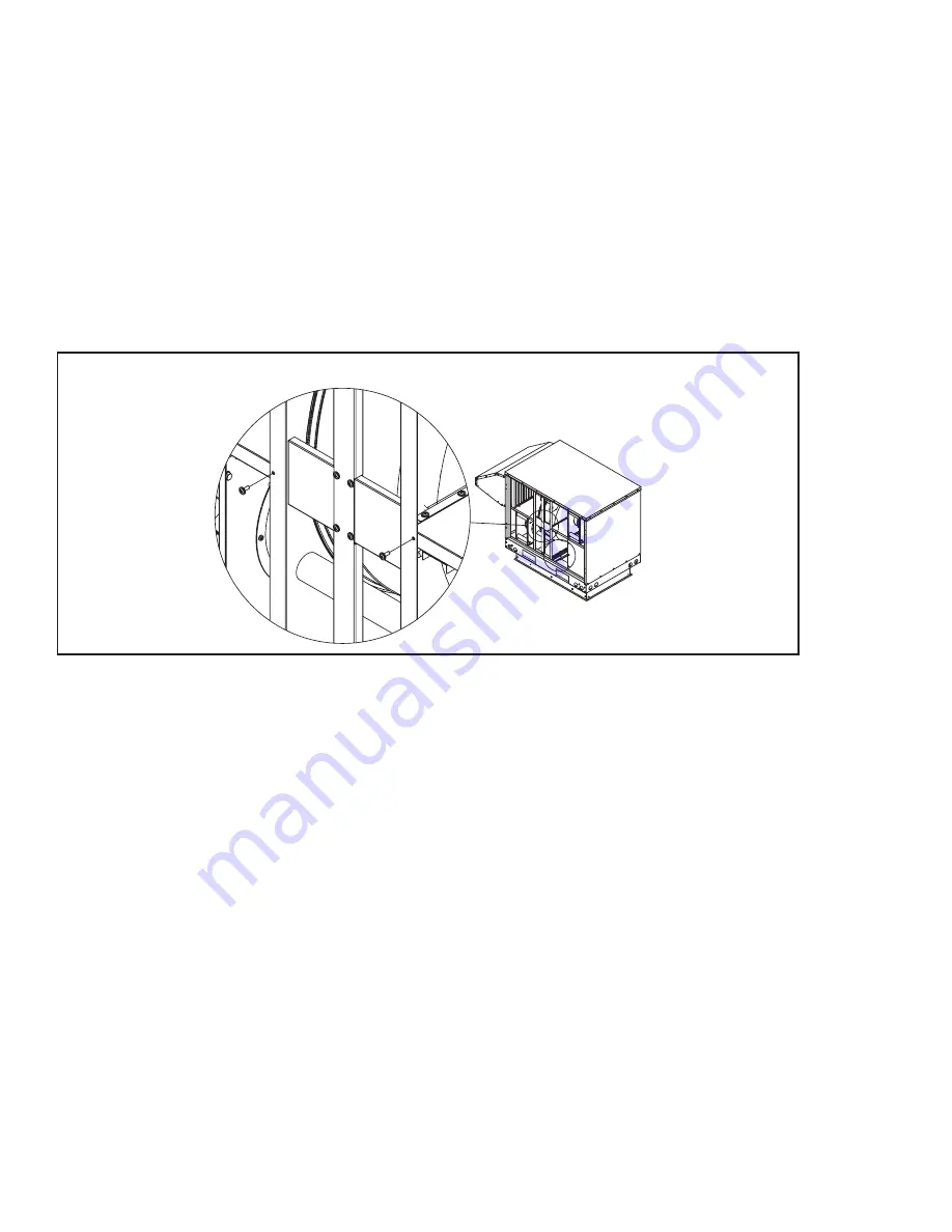
Figure 9: Bottom and front wheel hold down screws (one located on each side of the wheel)
MAINTENANCE OF DRIVE UNIT
The round belt is self tensioned and should not require any adjustment.
MAINTENANCE OF BRUSH SEALANTS
Tightness between brush sealants and casing needs to be checked during inspection. The brush sealants are easily adjusted by loosening the screws
and repositioning the brush sealant into the correct location. Round belt and brush sealants will be subject to wear and tear. Replacement parts can
be obtained from Systemair or any of its authorized dealers.
Options
Frost Prevention
This shall be accomplished by a preheater factory installed in the fresh air supply. Alternately, this may also be accomplished by a fan shut down strategy.
Dampers
All dampers shall be constructed of 16 gauge galvanized steel blades and hat channel frame with gasketed ends and edge seals unless noted differently.
The fresh air inlet hood may be equipped with a motorized damper. Exhaust air hood may be equipped with a motorized damper or with a gravity backdraft.
SYSTEMAIR ENERGY RECOVERY SYSTEM MAINTENANCE
Maintenance record
A record of regular maintenance is required to maintain any letters of guarantee issued by Systemair Inc. Date of service, actions taken, and the name of
the service person are required. Frequency of maintenance required should be determined by inspection. The Systemair Energy Recovery Unit requires
minimal maintenance in clean airstreams.
Maintenance procedure
Access to the Systemair Energy Recovery Unit is gained via access panels located on the front of the unit. Disconnect and lockout all power supply to
the ERV. Small amounts of dust present in either side of the energy recovery wheel will not affect the performance of the unit. If appreciable amounts
of dirt has accumulated, the energy recovery unit may be cleaned with a vacuum cleaner or the dirt may be blown out with compressed air. For ac-
cumulations proving more difficult to clean, Systemair recommends using hot water (180ºF) and/ or a mild detergent (Oakite or Liqualin). This will not
damage the wheel media but care must be taken not to wet the electrical motor. Cover the motor with a plastic bag before applying water to the energy
wheel. Disconnect wheel motor power supply and slide wheel cartridge out of the main enclosure. Six (6) retaining screws hold the wheel assembly in
place. See Figure 9 for screw locations. These must be removed to allow easy removal of the energy wheel. Spray mild detergent evenly across the
transfer surface. Water pressure of 20 to 55 PSI is recommended. Take care not to force sharp objects against the energy transfer surface, as this
could damage the energy transfer media.


