8
I56-3102-003
©2019 System Sensor. 7/8/2019
THREE-YEAR LIMITED WARRANTY
System Sensor warrants its enclosed product to be free from defects in materials and
workmanship under normal use and service for a period of three years from date of man-
ufacture. System Sensor makes no other express warranty for the enclosed product. No
agent, representative, dealer, or employee of the Company has the authority to increase
or alter the obligations or limitations of this Warranty. The Company’s obligation of this
Warranty shall be limited to the replacement of any part of the product which is found to
be defective in materials or workmanship under normal use and service during the three
year period commencing with the date of manufacture. After phoning System Sensor’s
toll free number 800-SENSOR2 (736-7672) for a Return Authorization number, send de-
fective units postage prepaid to: System Sensor Canada (3PL), c/o Kuehne and Nagel,
6335 Edwards Blvd., Mississauga, Ontario L5N 2W7, RA #__________. Please include
a note describing the malfunction and suspected cause of failure. The Company shall
not be obligated to replace units which are found to be defective because of damage,
unreasonable use, modifications, or alterations occurring after the date of manufacture.
In no case shall the Company be liable for any consequential or incidental damages for
breach of this or any other Warranty, expressed or implied whatsoever, even if the loss
or damage is caused by the Company’s negligence or fault. Some states do not allow
the exclusion or limitation of incidental or consequential damages, so the above limita-
tion or exclusion may not apply to you. This Warranty gives you specific legal rights, and
you may also have other rights which vary from state to state.
Please refer to insert for the Limitations of Fire Alarm Systems
TABLE 3. DETECTOR STATUS INDICATION
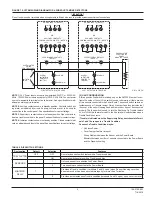
NOTE: There are two LED’s on the Power board D4P120A, each indicating the Status of the two sensors connected. When
there is only one sensor connected, LED2 will remain off.
Sensor
D4S
Power Board
D4P120
At power-up or reset at the panel, the
sensor will take approx 45 seconds
to initialize. Also occurs if the sensor
has been removed and restored in
the base in the sensor housing.
RED Blink every 5
seconds
Alternating
Green/amber
every 1 second
Supervisory relay
: Terminals 3 and 14 are open.
Alarm Relay
: Terminals 4 and 5 are open.
Aux Relay
does not switch states:Terminals 6 and 16 are closed,Terminals 8 and 18 are closed
Sensor is missing during the seven
minute tamper Delay, if selected.
Off
Alternating
Green/amber
every 1 second
Supervisory relay
: Terminals 3 and 14 are closed
Alarm Relay
: Terminals 4 and 5 are open.
Aux Relay
does not switch states:Terminals 6 and 16 are closed,Terminals 8 and 18 are closed
Maintenance
Sensor D4S is outside it's UL
approved sensitivity limits and needs
to be cleaned or replaced.
RED Blink every 5
seconds
Amber Blink
every 5 seconds
Supervisory relay
: Terminals 3 and 14 are
closed
.
Alarm Relay
: Terminals 4 and 5 are open.
Aux Relay
does not switch states:Terminals 6 and 16 are closed,Terminals 8 and 18 are closed
.Unit loses Power Off
Off
.Cover Tamper Delay times out
Green Blink every 5
seconds
Amber solid
.Wiring Problems between the
Sensor and the Power Board
Off
Amber solid
.Mismatch between the number of
sensors connected and the Dip
Switch setting
1 sensor connected,2 selected
Green blink every 5
seconds on first
sensor.
No second sensor.
LED1 Green
blink every 5
seconds
LED2 Amber
solid
2 sensors connected,1 selected
Green blink every 5
seconds on first
sensor.
LED's off on second
sensor
LED1 Green
blink every 5
seconds
LED2 Amber
solid
Alarm
Unit detects smoke
Solid Red
Solid Red
Supervisory relay
: Terminals 3 and 14 are closed
Alarm Relay
: Terminals 4 and 5 are closed.
Aux Relay
switches states: Terminals 6 and 16 are open, Terminals 8 and 18 are open
Standby
Unit has Power and it is not in
initialization, Trouble, Maintenance or
Alarm.
Green Blink every 5
seconds
Green Blink
every 5 seconds
Supervisory relay
: Terminals 3 and 14 are closed
Alarm Relay
: Terminals 4 and 5 are open.
Aux Relay
does not switch states: Terminals 6 and 16 are closed, Terminals 8 and 18 are closed
LED Status
Status
Description
Status of Relays
Supervisory relay
: Terminals 3 and 14 are open.
Alarm Relay:
Terminals 4 and 5 are open.
Aux Relay
does not switch states with no shutdown on Trouble selected:
Terminals 6 and 16 are closed. Terminals 8 and 18 are closed.
Aux Relay
Switches states with shutdown on Trouble selected:
Terminals 6 and 16 are open, Terminals 8 and 18 are open
Trouble
Sensor
Initialization


