


504
440
R2
6
2
337
280
237
237
153,5
153,5
28
72
0
132
192
432
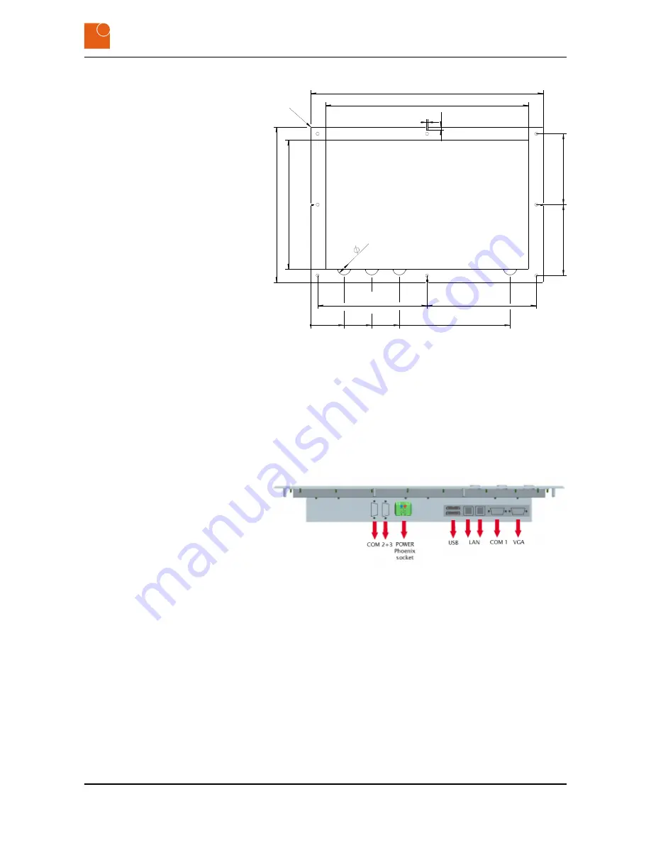
Fig. 9: Image of the wall template
3.5 External connections
3.5.1 Overview of external connections
The following illustration shows the connectors that are located on the
underside of the CONTROL 217 PC.
Fig. 10: Overview of the interfaces on the underside
3.5.2 Description of the external connections
Your device will not incorporate all of the following connectors (see
Ä
Chapter 3.3 “Technical data for the device” on page 13
).
Product description
External connections > Description of the external connections
CONTROL 217 PC - Industrial PC
17
Содержание CONTROL 217 PC
Страница 4: ...Table of contents CONTROL 217 PC Industrial PC 4 ...
Страница 6: ...General information Copyright notice CONTROL 217 PC Industrial PC 6 ...
Страница 10: ...Safety Important safety notes CONTROL 217 PC Industrial PC 10 ...
Страница 22: ...Product description Conformity CONTROL 217 PC Industrial PC 22 ...
Страница 26: ...Starting up Mounting the device CONTROL 217 PC Industrial PC 26 ...
Страница 34: ...Repairs CONTROL 217 PC Industrial PC 34 ...
Страница 38: ...Packaging and transport Transporting the device CONTROL 217 PC Industrial PC 38 ...
Страница 40: ...Disposal CONTROL 217 PC Industrial PC 40 ...