background image

5 – 1

i

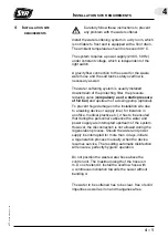
nsTallaTion

 / o

peraTion

 / s

TarT

-

up

5

©


 IT

 4000

  9.4000.04

  1148

5.1  i

nsTallaTion

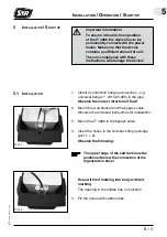
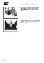
1.  Install a connection flange (accessories - e.g.  


universal flange 1", 2315.25.005) in the pipe.  


Observe the correct direction of flow!

2.  Mount the wall bracket and the bypass valve. 


Observe the enclosed instructions for installation.

3.  Mount the IT 4000 to the bypass valve. 

4.  Insert the hoses in the corresponding openings 


(pict. 1 + 2).


Observe the following: 

The upper edge of the salt tank must be 

positioned below the connection of the 

regeneration hose!

Important information!
To ensure a trouble-free operation 

of the IT 4000, the device has to be 

permanently connected to the power 

mains. Make sure that the device 

contains a sufficient amount of salt. 
The non-compliance with these 

instructions will damage the device!

Pict. 1

Pict. 2


Hose with red marking into body with red 


marking 


The opening in the middle has no function!

5.  Fix the hoses with cable straps.

5  i

nsTallaTion

 / s

TarT

-

up

Содержание IT 4000

Страница 1: ......

Страница 2: ......

Страница 3: ...1335 Korschenbroich Phone 49 0 2161 61 05 0 Fax 49 0 2161 61 05 20 Internet www syr de E Mail info syr de INSTRUCTIONS for USE and INSTALLATION IT 4000 Copyright Hans Sasserath Co KG The company Hans Sasserath Co KG remains the owner of the copyright of the present instructions manual No part of this publication may be reproduced transmitted in any form or by any means or used for competitive ends...

Страница 4: ......

Страница 5: ...works 3 1 4 Installation site requirements 4 1 5 Installation Operation Start up 5 1 5 1 Installation 5 1 5 2 Operation 5 3 5 3 Menu tree 5 4 5 4 Start up 5 5 6 Operation Interruption 6 1 6 1 Operation 6 1 6 2 Interruption 6 1 7 Maintenance Inspection Cleaning 7 1 7 1 Maintenance 7 1 7 2 Inspection 7 2 7 3 Cleaning 7 2 8 Malfunctions 8 1 8 1 Troubleshooting 8 2 9 Warranty 9 1 10 Diagrams 10 1 11 T...

Страница 6: ......

Страница 7: ... Prior to cleaning works on the device or close to it always unplug the apparatus as water and current form a lethal mixture The apparatus is delivered with a mains adapter Only qualified service technicians are authorized to install the device Ensure that the socket is always readily accessible When the cable of the device is damaged it has to be exchanged in order to avoid any risk Unplug the de...

Страница 8: ...d should not be touched Vent the water softening system right after the connection to the water mains to ensure per fect safety 1 5 Safety instructions Temperature Caution The indicated salt quantities refer to the use of salt tablets When using industrial salt salt pellets or blocks or fragmented salt quantities may vary ...

Страница 9: ...llow for the partial softening of both the total water in single multi family houses and of specific water quantities used for hot water swimming pools washing machines and dish washers Synthetic pipes or other corrosion resistant pipes shall be installed in all cases where water of 0 dH German hardness degree flows through the pipes Galvanized or copper tubes can be also used in case of partial s...

Страница 10: ... other claims To ensure trouble free functionality the regeneration salt used must comply with the requirements of the European Standard EN 973 We recommend Broxo or Solvay salt We recommend to conclude a service contract to make sure that the perfect functionality of all water treatment devices is verified on a regular basis ...

Страница 11: ...the soft water supply As a result the user always has soft water at his disposal even during regeneration The regeneration process requires only a small amount of salt and complies with EN 14743 The water softening system undergoes automatic disinfection on a regular basis in order to prevent microbial growth The small amount of chlorine required for that process is generated electrolytically from...

Страница 12: ...derable amount of water drawn off for instance caused by a flushing valve an overflow valve integrated in the control unit opens a bypass is opened which reduces the pressure loss and a small amount of water is not treated during that short moment As a result the hardness of the blended water is somewhat higher for a short while ...

Страница 13: ...re of 5 0 bar and upstream of a dosing pump optional To prevent huge damage on the installation site due to a leaking device or supply line for instance in an office medical practice etc it has to be ensured that during the personnel s absence the water and power supply are interrupted upstream of the system However the disconnection is not allowed during the regeneration process Should the water ...

Страница 14: ......

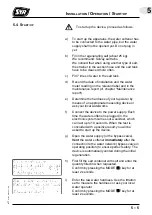
Страница 15: ...responding openings pict 1 2 Observe the following The upper edge of the salt tank must be positioned below the connection of the regeneration hose Important information To ensure a trouble free operation of the IT 4000 the device has to be permanently connected to the power mains Make sure that the device contains a sufficient amount of salt The non compliance with these instructions will damage ...

Страница 16: ... regeneration hose to the top of the control unit pict 1 and pull it through the left lateral insulation to the backside of the device pict 3 7 Fix the emergency overflow hose to the backside of the salt tank and direct it through the cover to the sewer pict 4 Pict 3 Pict 4 ...

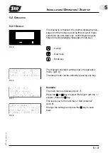
Страница 17: ...s and acknowledging messages mode key 5 2 1 Display The display s standard setting shows the operation mode pict 6 The sleep mode can be ended by pressing any key Up key Down key Mode key Pict 5 Pict 6 Example The main menu is displayed pict 7 Press the or key to select Refill salt with the symbol Press the key This leads you to the next menu Salt container pict 8 Change the settings and press the...

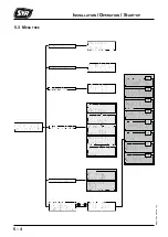
Страница 18: ...5 4 Installation Operation Start up IT 4000 9 4000 04 1148 5 3 Menu tree ...

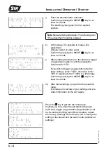
Страница 19: ... device or ask your local waterworks f Connect the device to the power supply Each time the water softener is plugged in the electronic system carries out a self test which can last up to 10 seconds When the test is concluded with a positive result you will be asked to start up the device g Open the water supply or the bypass valve Vent the water softener immediately after the connection to the wa...

Страница 20: ...utlet Advanced settings Note Measuretheblendedwater Thefollowingpoint Fine adjustment might be skipped k At this stage it is possible to make a fine adjustment Choose harder or softer water Confirm by pressing the MODE key for at least 2 seconds l When starting the device for the first time trigger a regeneration cycle to vent the installation Confirm with YES If you wish to trigger a regeneration...

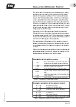
Страница 21: ...lation of the sodium content allows to determine whether the blended water is still in compliance with this maximum value of the sodium content When the calculated total sodium content exceeds the admissible value of 200 mg l adjust the setting of the blended water hardness to a higher value Table 1 Calculation of the sodium content Calculation of the sodium content dH Raw water hardness ask water...

Страница 22: ......

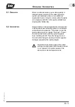
Страница 23: ... a manual regeneration process when a dismounted water softening system is re installed and put back into operation This allows to vent the water softener refer to chapter Start up Protect the dismounted water softening system against frost humidity and dirt Place the flange cover on the connection flange to provide protection against damages especially the sealing edges Should the main water supp...

Страница 24: ......

Страница 25: ...mary filtrate pos 5 is reached At this stage the resin is flushed downwards waste water 2 5 4 litres f After two further lifts the regeneration of the first tank is completed The driver now turns with two lifts the right gear wheel to the position Influx of salt pos 2 to regenerate the second tank Afterwards the system initiates another lift waste water quantity roughly 4 5 l g The backwash positi...

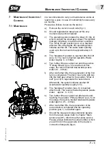
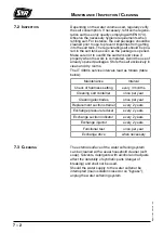
Страница 26: ...lusively in clean and dry rooms The IT 4000 s service intervals read as follows table below 7 3 Cleaning 7 2 Inspection The external surface of the water softening system can be cleaned with a usual household cleaner soft soap Solvents detergents with alcohol and lacquers affect the durability of synthetic parts danger of breaking and shall not be used Should the water supply to the water softener...

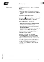
Страница 27: ...pipe pressure as salt has not been refilled in due time by manual rotation of the driving wheel during A regeneration process or by an operating error for instance when setting the hardness level refer to chapter Start up confirm the malfunction message and initiate a regeneration process manually When there is no further error the system automatically goes back to trouble free operation If a malf...

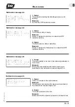
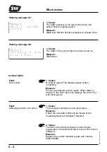
Страница 28: ... too low Measure Ensure that the dynamic pressure is at least 2 bar Malfunction message A1 1 Cause The water supply has been stopped during regeneration Measure Restore the water pressure Unplug the device and turn the driving wheel clockwise with a spanner of size 13 until reaching the operating position position 1 cf chapter 7 1 Plug in again and initiate regeneration 2 Cause The water pressure ...

Страница 29: ...e Malfunction message A4 1 Cause The turbine is dirty or faulty Measure Clean or replace the turbine or contact the SYR customer service 2 Cause The Hall sensor is dirty or defective Measure Clean or replace the Hall sensor or contact the SYR customer service Malfunction message A5 Malfunction message A6 2 Cause The water pressure is too low Measure Make sure that the dynamic pressure is at least ...

Страница 30: ... The display always shows something Measure Ensure a permanent power supply When water is drawn off the forth menu line displays the word Flow with moving bars Fault No function Fault Softening function not correct 1 Cause The raw water hardness is not set properly Measure Check the raw water hardness by means of the measuring device and adjust if required 2 Cause The ball in the suction indicator...

Страница 31: ...sure reducing valve spare part number 3000 00 917 1 Cause There is a malfunction in the control unit Measure To reset the device unplug press and hold the manual regeneration button while plugging in again Fault The device gets stuck at some point during regeneration 2 Cause The dynamic pressure has fallen below 2 bar during regeneration Measure To reset the device unplug press and hold the manual...

Страница 32: ...operly Measure Mount the hose on a fitting and check the connections Fault Leaking hose 1 Cause The hardness difference is too big Measure Adjust the hardness setting Stick to the sodium calculation in the instructions manual chapter 5 7 Fault The water has a salty taste ...

Страница 33: ...ntenance works and provide the necessary consumables or wear out parts etc The warranty period lasts 24 months as of the date of installation We commit ourselves to repair or replace as quickly as possible all parts that become unserviceable during the warranty period as a result of verifiably bad materials a defective construction or a faulty model Our highest objective is to manufacture high qua...

Страница 34: ......

Страница 35: ...r day Pressure loss in operating position pos 1 with a raw water hardness of 20 dH German hardness degree and a blended water hardness of 8 dH in dependence on the volume tric flow rate Max possible draw off quantity per day depending on the raw water hardness with a blen ded water hardness of 8 dH German hardness degree ...

Страница 36: ... water quantity Max possible permanent draw off quantity depending on the raw water hardness with a blended water hardness of 8 dH German hardness degree Waste water quantity per 1 m3 of blended water with a 8 dH hardness German hardness degree in dependence on the raw water hardness ...

Страница 37: ...10 3 Diagrams 10 IT 4000 9 4000 04 1148 Salt consumption per 1 m3 of blended water with a 8 dH German hardness degree hard ness in dependence on the raw water hardness Fig 5 Salt consumption ...

Страница 38: ......

Страница 39: ...e Pressure loss at nominal flow rate Stock level of salt Power supply Salt consumption and waste water per m3 as well as pressure loss and max draw off quantity Volume of exchanger resin Weight with salt fill 1 7 m3 h 0 9 mol PN 10 5 mol 2 bar 7 0 bar the central installation of a pressure reducing valve is compulsory as of a dynamic pressure of 5 0 bar chapter 4 1 30 C 0 8 bar 40 kg 230V 50Hz 15W...

Страница 40: ......

Страница 41: ...neration cartridge 3000 00 907 Suction indicator 3000 00 908 Bypass valve 3000 00 909 Pressure reducing valve 3000 00 917 Suction strainer 3000 00 912 Regenerating salt 25kg 3000 00 911 Bypass valve 1700 00 000 Titration test IT 4000 3000 00 913 Maintenance kit 3000 00 920 2 3 4 Exchange intervals 1 year 2 years 3 years 4 years Y distribution flange multi flange 2315 00 071 Double connection flang...

Страница 42: ...00 04 1148 Connection flange not included in delivery Length of connection hose up to salt container 1 3m Water softener Salt container Nominal size DN 20 32 Dimensions T mm 433 t mm 470 B mm 455 b mm 455 H mm 980 h mm 354 h1 mm 141 h2 mm 522 ...

Страница 43: ... 3 Position 3 4 Position 5 The values for suction time waste water flushing and primary filtrate apply to each regeneration step Date of installation Mains pressure Date Raw water hardness measured dH set dH Hardness of blended water measured dH Water meter m3 Number of reg 1 S L N M Suction time 2 minu tes max 15 min Waste water litres max 4 5 litres Flushing 3 3 4 5 litres Primary filtrate 4 2 5...

Страница 44: ......
Отзывы: