resistance of the diode ring changes with the control current. Q7 is the resonance amount
control element and Q10 is the filter frequency voltage control element.
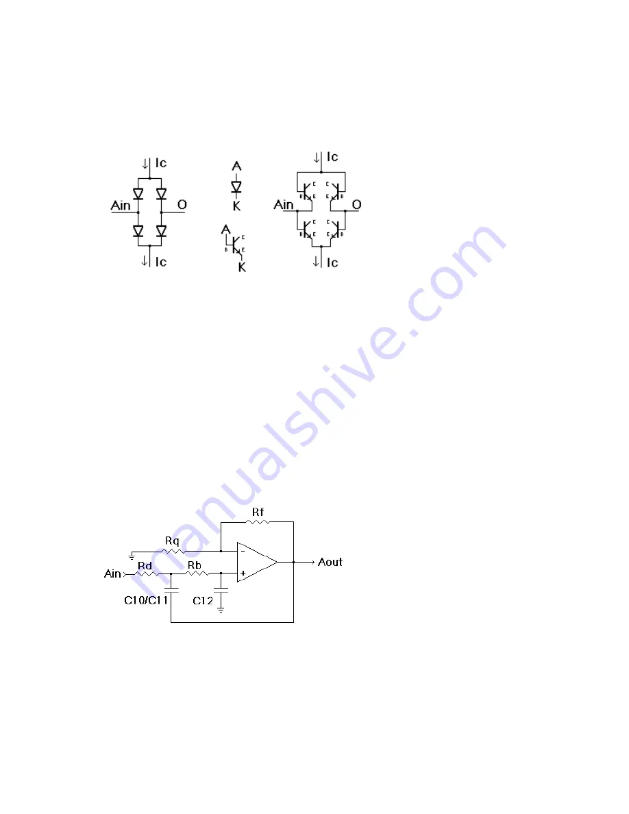
If it is difficult understanding how a transistor can be a diode, look at it the following
image:
The canonical diode ring is illustrated on the on the left, where “Ain” is the signal input,
“O” is the signal output and “Ic” are the control current source input (top) and output sink
(bottom). Since a diode is a P-N junction device, with the P material called an anode and
the N material called the cathode for their natures of harboring “positive” (an)ions or
“negative” (cat)ions, it should then be apparent that a bipolar transistor, in this case N-P-N
junction devices, can act as diodes if one junction is left unused (traditionally the collector).
Thus, the “bases” of our NPNs become anodes and the “emitters” become cathodes, and we
get the diode ring made from transistors as shown on the right.
The Sallen-Key Filter Model Using Diode Rings
The classic 12dB/octave (or decade) Sallen-Key lowpass model can be drawn as:
For the MOTM-485 circuit, think of Rd as the diode bridge Q10, Rb as R48, Rf as R47 and
Rq as the R23+R37+TP1+C9+Q7 chain. Yes, there is a capacitor in there (never mind a
transimpedance diode cell made from Q7) but we’re dealing with AC impedance so think of
it as a resistor. It is much easier that way. The op-amp? We’ll get to that.
SYNTHESIS TECHNOLOGY
PAGE
13
MOTM-485 ASSEMBLY 8/11/05
WWW.SYNTHTECH.COM
Содержание MOTM-485 GX-1 Diode VCF
Страница 19: ......


