6.
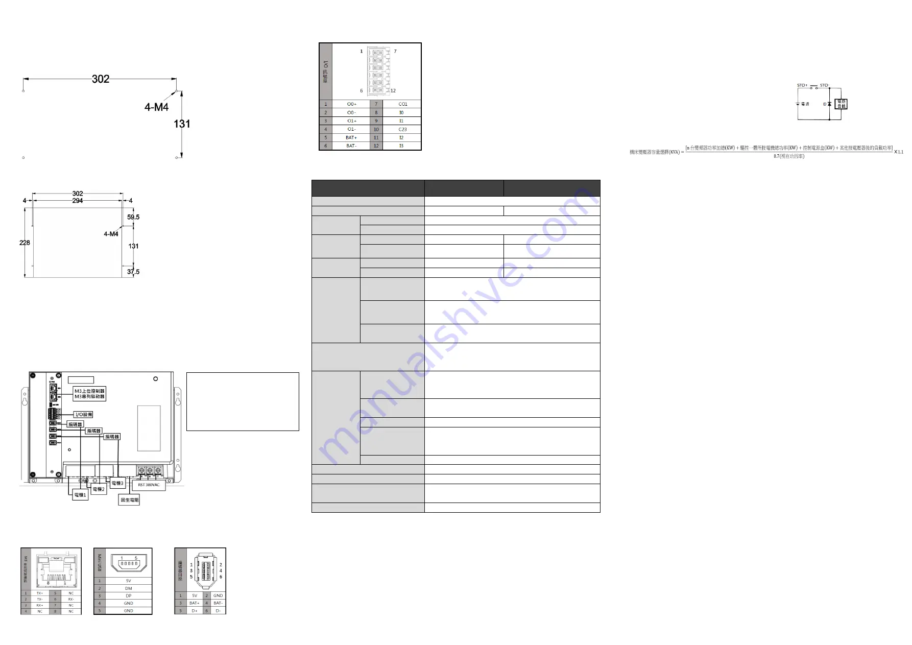
Mounting Hole Specification (Unit: mm)
Please install with M4 screws.
⚫
Default Settings
⚫
Recommended Arrangement of Heat Dissipation
7.
Basic Wiring Diagram
Please Confirm whether the wiring of the U, V, W terminals output to the motor is
correct, otherwise it may cause reversal or abnormality, and the encoder must be
adjusted again.
When wiring the host controller, either the general servo signal or the serial servo
signal can be installed.
8.
Interface Configurations
Please notice the value and polarities of voltages.
Serial Communication
Mini USB Port
Encoder Feedback
Port Arrangement
Arrangement
Arrangement
I/O Signal Port Arrangement
9.
Driver Specifications
Type
S08-SMD33B2575-00
S08-SMD33B35100-00
Input Voltage
AC 3PH 380~460V 50/60Hz
Input Current
46A
65A
Output Voltage
Axis1~Axis2
AC 3PH 0~440V 0~400Hz
Axis4
AC 3PH 0~440V 0~400Hz
Rated output
current
Axis1~Axis2
5.4A
8.4A
Axis4
21A
27A
Rated Power
Axis1~Axis2
1.5kW
2kW
Axis4
7.5kW
11kW
Terminal
Specifications
RST
、
PBN
、
U
4
V
4
W
4
Wire Specifications: 65A 14~6AWG/85A 4AWG(Sol)/100A 4~3 AWG(Str)
Operating Temperature: --40
℃
~+130
℃;
Rated Torque: 2.4N
‧
m
U
1
V
1
W
1
~U
2
V
2
W
2
Wire Specifications: 30~10 AWG
;
Operating Temperature: --40
℃
~+105
℃;
Rated Torque: 0.69N
‧
m
I/O Signal Port
ADDA Second Feedback
Wire Specifications: 28~16 AWG; Operating Temperature: -40
℃
~+115
℃
Power Source Environment
TN System
(1)
Allowable voltage deviation: -15% ~ +10%
Allowable frequency deviation: -5% ~ +5%
Environment
Condition
Temperature
Operating: 0
℃
~ 55
℃
(Not frozen. If the ambient temperature
exceeds 45
℃
, the air circulation system must be activated.)
Storage/Transporting: -20
~
65
℃
(Not frozen)
Humidity
Operating: Below 90%RH (Not condensed)
Storage/Transporting: Below 90%RH (Not condensed)
Surrounding Area
In door (Avoid direct sunlight), avoid corrosive gas, avoid flammable gas
Height
Operating/Storage Altitude (Max.): 1,000 meters
(With derating, usage is possible between 1,000 m and 2,000 m.)
Transporting Altitude (Max.): 10,000 meters
Vibration
5.9 m/s
2
Pollution Degree
2
IP Level
IP10
Frame Size
W
×
H
×
D mm
315 x 212 x 220
Weight
7.5Kg
NOTE
:
(1)
TN System: The neutral point of the power system is grounded directly to earth, and the exposed metal components
are grounded by protective earthing conductors.
10.
Wiring Notifications
⚫
When using a solenoid valve or other inductive loads, please apply an arc
extinguisher, an RC varistor, or a flyback diode to ensure the life of the contact
points. Advantages of the arc extinguisher:
1)
Extend the life of electrical contacts.
2)
Reduce the sparks from the contact points.
3)
Restrain the impulse voltage.
4)
Prevent the inductive loads from interferences
caused by back EMF.
⚫
Suppose a client wants to drive four 1.2kW motors with 1kW*4 Servo Drive
Embedded Controller, it means the gross power should supply at most 4.8kW. Then
we reverse the formula and set the power factor at 0.7. If only Servo Drive
Embedded Controllers are used, the capacity should be at least 4.8/0.7=6.85kVA. In
addition, 10% of the backup capacity should be considered. Thus, 7.5kVA would be
more suitable. Moreover, if an inverter is used, and the power is supplied by an
isolation transformer, the capacity of the inverter should be considered.
Do not connect a cable with other cables to extend the length. It might cause signal
error or malfunction.
Please crimp or weld the wire connections while doing the wirings.
If the servo line in use is not a standard Syntec cable, please verify all the terminals
connected properly before power-on. Wrong wirings will lead to controller output
command errors and malfunctioning.
The +5V output capacity of the encoder is 500mA and is only for a single encoder.
Do not connect it with other loads or it might cause error due to the lack of driving
force.
Do not use counterfeit terminal strips. Those terminal strips cannot provide overall
protection for the system. The quality is also not guaranteed and tend to cause
electrical control problems of the machine tools.
The wiring of the driver and the motor cannot be pulled too tightly.
Do not stake on top.
The six power lines, R, S, T and U, V, W, should not be close to other signal lines,
and should be at least 30 cm apart.
After cutting off the power, the capacitor of the driver still contains large amount of
charge. Do not touch the 6 power lines, R, S, T and U, V, W, until the power
indicator goes out.
If the encoder line should be longer, please use twisted-pair and signal cable with
isolated ground. Do not extend it over 20 meters. In case of extensions over 20
meters, please double the wire diameter of signal cables to reduce signal attenuation.
To ensure the quality of communication, the USB extension cord in use should not
exceed 5 meters, and do not use for charging purposes to avoid controller failure.
The drive is fragile. Please handle it with care.
Do not allow conductive foreign matter such as screws or metal chips, or combustible
foreign matter such as oil enter the driver.
※
Recommended Encoder
Wire Diagram:
22AWG
×
2C+24AWG
×
2P
Over 90% coverage.
▲
Flyback diode circuit diagram


