Syntax S740M Скачать руководство пользователя страница 27


23 

C

C

o

o

n

n

n

n

e

e

c

c

t

t

i

i

n

n

g

g


I

I

/

/

O

O


D

D

e

e

v

v

i

i

c

c

e

e

s

s


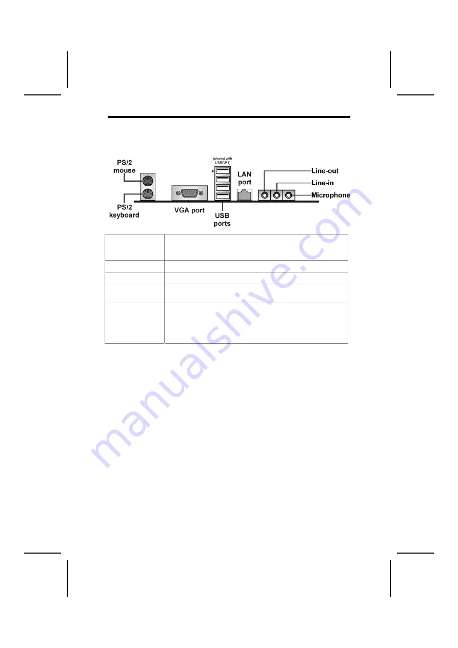
The backplane of the mainboard has the following I/O ports: 


PS/2 Mouse and 
Keyboard 

The mainboard provides a standard PS/2 mouse/keyboard mini 
DIN connector for attaching a PS/2 mouse/keyboard. You can 
plug a PS/2 mouse/keyboard directly into this connector. 

VGA Port 

Connect your VGA monitor to this port. 

USB Ports  

You can plug any USB device into one of the USB ports.


LAN Port  
(optional) 

Connect an RJ-45 jack to the LAN port to connect your 
computer to the Network. 

Audio Ports  

The Line-in jack can be connected to devices such as a 
cassette or minidisk player to playback or record. The Line-out 
jack is used to connect speakers or headphones for audio 
output. The Microphone-in jack can be connected to a 
microphone for voice input. 

Содержание S740M

Страница 1: ...ested and found to comply with the limits for a Class B digital device pursuant to Part 15 of the FCC Rules These limits are designed to provide reasonable protection against harmful interference in a residential installation This equipment generates uses and can radiate radio frequency energy and if not installed and used in accordance with the instructions may cause harmful interference to radio...

Страница 2: ...terference causing Equipment Regulations Cet appareil numérique de la classe B respecte toutes les exigences du Réglement sur le matériel brouilieur du Canada About the Manual The manual consists of the following Chapter 1 Introducing the Mainboard Describes features of the mainboard and provides a shipping checklist Go to page 1 Chapter 2 Installing the Mainboard Describes installation of mainboa...

Страница 3: ...g List Translations iii CHAPTER 1 1 Introducing the Mainboard 1 Introduction 1 Checklist 1 Standard Items 1 Features 2 Choosing a Computer Case 4 Mainboard Components 5 CHAPTER 2 8 Installing the Mainboard 8 Safety Precautions 8 Quick Guide 8 Installing the Mainboard in a Case 9 Checking Jumper Settings 9 Setting Jumpers 9 Checking Jumper Settings 10 ...

Страница 4: ...iguration 25 Running the Setup Utility 26 Using BIOS 27 Standard CMOS Setup 27 Advanced CMOS Setup 28 Advanced Chipset Setup 29 Power Management Setup 30 PCI Plug and Play Setup 32 Peripheral Setup 33 Hardware Monitor Page 34 Change Supervisor User Password 35 Auto Configuration with Optimal Settings 36 Auto Configuration with Fail Safe Settings 36 Save Settings and Exit 36 Exit Without Saving 36 ...

Страница 5: ... port a PS 2 keyboard connector mouse connector and audio jacks for microphone line in and line out Two PCI local bus slots and one communication and networking riser CNR slot provide expandability for add on peripheral cards It also comes with a built in Enhanced PCI Bus Master PCI IDE controller that provides high speed connections to full range of IDE devices such as HDD and CD ROM This mainboa...

Страница 6: ...ec Additional key features include support for six USB ports an AC 97 link for audio and modem hardware monitoring and ACPI OnNow power management USB 2 0 The USB 2 0 Controller is compliant with Universal Serial Bus Specification Revision 2 0 The USB 2 0 supports data transfer rates up to 480MB sec for high speed devices and specifies a microframe that will be 1 8 th of a 1msec frame This allows ...

Страница 7: ...rs Two PS 2 ports for mouse and keyboard One VGA port Four USB ports One LAN port Audio jacks for microphone line in and line out Onboard LAN optional The VT6103L is a Physical Layer device for Ethernet 10BASE T and 100BASE TX using category 5 Unshielded Type 1 Shielded and Fiber Optic cables Dual Speed 100 10 Mbps Half And Full Duplex Meet All Applicable IEEE 802 3 10Base T and 100Base Tx Standar...

Страница 8: ...ase Ensure that your case supports all the features required The mainboard can support one or two floppy diskette drives and four enhanced IDE drives Ensure that your case has sufficient power and space for all the drives that you intend to install Most cases have a choice of I O templates in the rear panel Make sure that the I O template in the case matches the I O ports installed on the rear edg...

Страница 9: ...5 M Ma ai in nb bo oa ar rd d C Co om mp po on ne en nt ts s S740M Without CPU onboard ...

Страница 10: ...6 S740MP With CPU onboard ...

Страница 11: ...processors CPUFAN1 Cooling fan for CPU DDR1 DDR2 Two 184 pin DIMM sockets EZJ1 EZ Watcher interface header IDE 1 Primary IDE channel IDE 2 Secondary IDE channel JP1 Clear CMOS jumper JP3 BIOS protect jumper PANEL1 Connector for case front panel switches and LED indicators PCI1 PCI2 Two 32 bit add in card slots RF1 IR Mouse header SPDIF1 SPDIF out header SJ1 Single color LED header SMI1 System Mana...

Страница 12: ...uit boards by the edges Do not bend circuit boards Q Qu ui ic ck k G Gu ui id de e This Quick Guide suggests the steps you can take to assemble your system with the mainboard The following table provides a reference for installing specific components Locating Mainboard Components Go to page 3 Installing the Mainboard in a Case Go to page 9 Setting Jumpers Go to page 9 Installing Case Components Go...

Страница 13: ...e appropriate 1 Place the mainboard over the mounting brackets Ensure that your case has an I O template that supports the I O ports and expansion slots on your mainboard C Ch he ec ck ki in ng g J Ju um mp pe er r S Se et tt ti in ng gs s This section explains how to set jumpers for correct configuration of the mainboard Setting Jumpers Use the mainboard jumpers to set system configuration option...

Страница 14: ...umper to clear the contents of the CMOS memory You may need to clear the CMOS memory if the settings in the Setup Utility are incorrect and prevent your mainboard from operating To clear the CMOS memory disconnect all the power cables from the mainboard and then move the jumper cap into the CLEAR setting for a few seconds Jumper 3 Enables you to prevent the BIOS from being updated flashed Set the ...

Страница 15: ...ct the case cooling fan connector to CASFAN1 4 Connect the case speaker cable to SPEAKER 5 Connect the case LED cable to SJ1 6 Connect the case switches and indicator to PANEL1 ATX1 ATX 20 pin Power Connector Pin Signal Name Pin Signal Name 1 3 3V 11 3 3V 2 3 3V 12 12V 3 Ground 13 Ground 4 5V 14 PS ON 5 Ground 15 Ground 6 5V 16 Ground 7 Ground 17 Ground 8 PWRGD 18 5V 9 5VSB 19 5V 10 12V 20 5V CPUF...

Страница 16: ...aker Pin Signal Name 1 Signal 2 Key 3 Ground 4 VCC SJ1 Single color LED header Pin Signal Name Function 1 ACPI LED MSG LED green 2 ACPI LED MSG LED green 3 SB5V Power LED ACPI LED function S0 S1 S4 S5 SJ1 1 Light Blinking Dark ...

Страница 17: ... an IDE drive should be connected to the onboard IDE interface The LED will also show activity for devices connected to the SCSI hard drive activity LED connector Power Sleep Message Waiting LED Connecting pins 2 and 4 to a single or dual color front panel mounted LED provides power on off sleep and message waiting indication Reset Switch Supporting the reset function requires connecting pins 5 an...

Страница 18: ...ing the Processor This mainboard automatically determines the CPU clock frequency and system bus frequency for the processor You may be able to change these automatic settings by making changes to jumpers on the mainboard or changing the settings in the system Setup Utility We strongly recommend that you do not overclock processors or other components to run faster than their rated speed Warning O...

Страница 19: ...g lever to the upright position 2 Match the corner on the CPU marked with an arrow with pin A 1 on the CPU socket the corner with the pinhole noticeably missing Insert the processor into the socket Do not use force 3 Swing the locking lever down and hook it under the latch on the edge of the socket 4 Apply thermal grease to the top of the CPU 5 Lower the CPU cooling fan heatsink assembly onto the ...

Страница 20: ... depending on whether the bus is 100 MHz or 133 MHz Double Data Rate SDRAM DDR SDRAM doubles the rate to 1 6 GBps and 2 1 GBps DDR SDRAM uses additional power and ground lines and requires 184 pin DIMM modules rather than the 168 pin DIMMs used by SDRAM Do not remove any memory module from its antistatic packaging until you are ready to install it on the mainboard Handle the modules only by their ...

Страница 21: ...ry and secondary IDE channel interface IDE1 and IDE2 An IDE ribbon cable supporting two IDE devices is bundled with the mainboard If you want to install more than two IDE devices get a second IDE cable and you can add two more devices to the secondary IDE channel IDE devices have jumpers or switches that are used to set the IDE device as MASTER or SLAVE Refer to the IDE device user s manual When i...

Страница 22: ...rive that you have installed Installing a CD ROM DVD Drive 1 Install the CD ROM DVD drive into the drive cage in your system case 2 Plug the IDE cable into IDE1 A If you have already installed an HDD use the other connector on the IDE cable Note Ribbon cable connectors are usually keyed so that they can only be installed correctly on the device connector If the connector is not keyed make sure tha...

Страница 23: ...em and Audio functionality Note Before installing an add on card check the documentation for the card carefully If the card is not Plug and Play you may have to manually configure the card before installation Follow these instructions to install an add on card 1 Remove a blanking plate from the system case corresponding to the slot you are going to use 2 Install the edge connector of the add on ca...

Страница 24: ...UD_MIC Front Panel Microphone input signal 2 AUD_GND Ground used by Analog Audio Circuits 3 AUD_MIC_BIAS Microphone Power 4 AUD_VCC Filtered 5 V used by Analog Audio Circuits 5 AUD_FPOUT_R Right Channel Audio signal to Front Panel 6 AUD_RET_R Right Channel Audio signal to Return from Front Panel 7 HP_ON Reserved for future use to control Headphone Amplifier 8 KEY No Pin 9 AUD_FPOUT_L Left Channel ...

Страница 25: ...gnment as indicated above A different pin assignment may cause damage or system hang up USBCR1 USB Card Reader connector This connector is for connecting internal USB card reader You can use a card reader to read or transfer files and digital images to your computer Pin Signal Name Function 1 USBVCC2 5V dual 2 USB2 Data signal port 2 3 USB2 Data signal port 2 4 GND Ground 5 Key No pin Note The USB...

Страница 26: ...set as line out port for 4 channel function Pin Signal Name Function 1 AUX_L AUX In left channel 2 GND Ground 3 GND Ground 4 AUX_R AUX In right channel EZJ1 EZ Watcher interface header This connector is for use with EZ Watcher interface only The EZ Watcher allows you to adjust the CPU frequency according to your desire Pin Signal Name Pin Signal Name 1 PCDAT 2 PCREQ 3 SCI 4 PCIRST 5 GND 6 VCC 7 GN...

Страница 27: ...ctly into this connector VGA Port Connect your VGA monitor to this port USB Ports You can plug any USB device into one of the USB ports LAN Port optional Connect an RJ 45 jack to the LAN port to connect your computer to the Network Audio Ports The Line in jack can be connected to devices such as a cassette or minidisk player to playback or record The Line out jack is used to connect speakers or he...

Страница 28: ...Audio line out Lime Digital monitor flat panel White Microphone Pink MIDI game Gold Parallel Burgundy PS 2 compatible keyboard Purple PS 2 compatible mouse Green Serial Teal or Turquoise Speaker out subwoofer Orange Right to left speaker Brown USB Black Video out Yellow SCSI network telephone modem None This concludes Chapter 2 The next chapter covers the BIOS ...

Страница 29: ...drives diskette drives and peripherals Video display type and display options Password protection from unauthorized use Power management features The settings made in the Setup Utility affect how the computer performs Before using the Setup Utility ensure that you understand the Setup Utility options This chapter provides explanations for Setup Utility options The Standard Configuration A standard...

Страница 30: ...scape key To cycle through the Setup Utility s optional color schemes press down the F2 F3 Some of the options on the main menu page lead to tables of items with installed values In these pages use the cursor arrow keys to highlight the items and then use the PgUp and PgDn keys to cycle through the alternate values for each item Other options on the main menu page lead to dialog boxes that require...

Страница 31: ...sor arrow keys to scroll through the items in the submenu In this manual default values are enclosed in parenthesis Submenu items are denoted by a triangle Standard CMOS Setup The Standard CMOS setup is used to modify basic system configuration data such as date time floppy and hard disk drive types video type and keyboard Date Time Use these items to set the system date and time Floppy Drive A Fl...

Страница 32: ...ou enable this item the system will also search for other boot devices if it fails to find an operating system from the first two locations Initial Display Mode BIOS This option specifies the initial display mode when the system boots S M A R T for Hard Disks Disabled Set this option to Enabled to permit the BIOS to use the SMART System Management and Reporting Technologies protocol for reporting ...

Страница 33: ...most of the system options in the computer You should leave the items on this page at their default values if you change the values incorrectly you may introduce fatal errors or recurring instability into your system Current Base Frequency 100 100 MHz This option allows you to select the current CPU DRAM frequency for your CPU Host Frequency 100 MHz This item displays the host frequency This is a ...

Страница 34: ...trobe We recommend that you leave this item at the default value Share Memory Size 32 MB This item allows you to select the shared memory size for VGA usage Power Management Setup The Power Management Setup Menu option is used to change the values of the chipset registers for system power management Power Switch Type On Off This option specifies how the power button is used In the Suspend mode the...

Страница 35: ... Alarm Resume From Soft Off Disabled This option enable or disable the RTC alarm to wake up the system from Soft Off Resume On RTC Alarm Date Hour Minute Second The system can be turned off with a software command If you enable this item the system can automatically resume at a fixed time based on the system s RTC realtime clock Use the items below this one to set the date and time of the wake up ...

Страница 36: ...item controls how long each PCI device can hold the bus before another takes over When set to higher values every PCI device can conduct transactions for a longer time and thus improve the effective PCI bandwidth Primary Graphics Adapter PCI This item indicates if the primary graphics adapter uses the PCI or the AGP bus Allocate IRQ to PCI VGA Yes If this item is enabled an IRQ will be assigned to...

Страница 37: ...serve IRQs for legacy ISA adapter cards and determine if the BIOS should remove an IRQ from the pool of available IRQs passed to devices that are configurable by the system BIOS The available IRQ pool is determined by reading the ESCD NVRAM If more IRQs must be removed from the pool the end user can use these options to reserve the IRQ by assigning an ISA EISA setting to it Onboard I O is configur...

Страница 38: ...is item to enable to support for older keyboard and mouse devices if the USB option is set to enable Onboard PCI IDE Both Use this item to enable or disable either or both of the onboard Primary and Secondary IDE channels Hardware Monitor Page This section sets some of the parameters for the hardware monitoring function of this mainboard CPU Vcore Voltage Set this field to match the voltage of the...

Страница 39: ...Esc to abort the selection To disable password just press Enter when you are prompted to enter password A message will confirm the password being disabled Once the password is disabled the system will boot and you can enter BIOS Setup freely PASSWORD DISABLED If you have selected System in Security Option of BIOS Features Setup menu you will be prompted for the password every time the system reboo...

Страница 40: ... functioning correctly try installing the fail safe defaults as a first step in getting your system working properly again If you only want to install fail safe defaults for a specific option select and display that option and then press F6 Save Settings and Exit Highlight this item and press Enter to save the changes that you have made in the Setup Utility and exit the Setup Utility When the Save...

Страница 41: ...or something similar These files may contain important information that is not included in this manual A Au ut to o i in ns st ta al ll li in ng g u un nd de er r W Wi in nd do ow ws s 9 98 8 M ME E 2 20 00 00 0 X XP P The Auto install CD ROM makes it easy for you to install the drivers and software for your mainboard Note If the Auto install CD ROM does not work on your system you can still insta...

Страница 42: ...ly Some software is installed in separate folders for different operating systems such as DOS WIN NT or WIN98 95 Always go to the correct folder for the kind of OS you are using To install the software execute a file named SETUP EXE or INSTALL EXE by double clicking the file and then following the instructions on the screen Exit The Exit button closes the Auto Setup window Application Tab Lists th...

Страница 43: ...owing screen appears 3 Check the box next to the items you want to install The default options are recommended 4 Click Next run the Installation Wizard An item installation screen appears 5 Follow the instructions on the screen to install the items Drivers and software are automatically installed in sequence Follow the onscreen instructions confirm commands and allow the computer to restart a few ...

Страница 44: ...r copied in accordance with the terms of the license Note These software s are subject to change at anytime without prior notice Please refer to the support CD for available software AWARD Flash Memory Utility This utility lets you erase the system BIOS stored on a Flash Memory chip on the mainboard and lets you copy an updated version of the BIOS to the chip Proceed with caution when using this p...

Страница 45: ... to install the application software Super Voice Fax Modem Software To install the Super Voice voice fax data communication application for use with the built in fax modem go the directory UTILITY SUPER_VOICE then run PICSHELL EXE to install the application software PageABC The PageABC application software enables you to create your very own home page To install the PageABC go to the directory UTI...

Отзывы: