background image


15

  Chapter 2: Hardware Setup

To make sure UC3200 recognizes the new memory capacity:

Log in to DSM UC as 

admin

 or a user belonging to the 

administrators

 group.

Check 

Total Physical Memory

 in 

Control Panel

 > 

Info Center

.

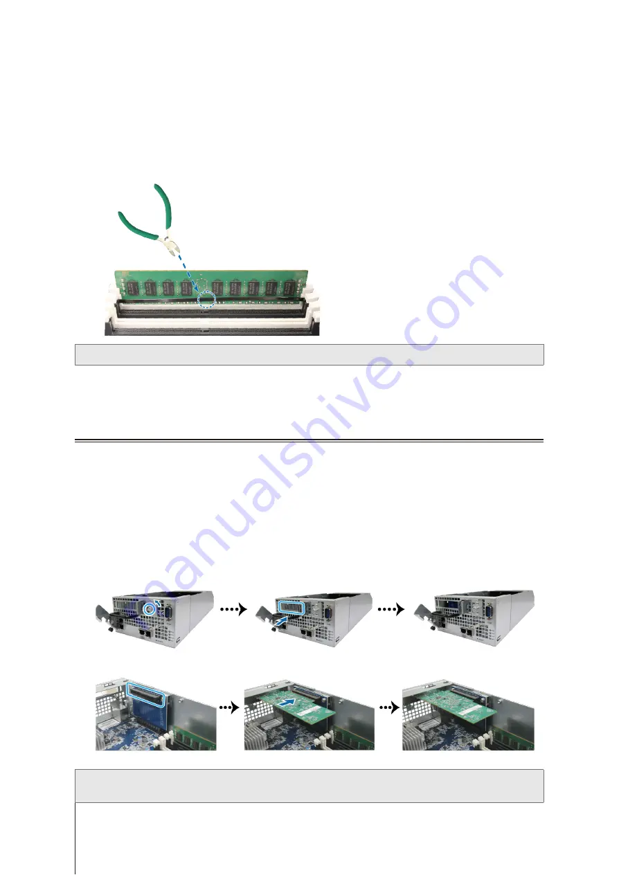
To remove the RAM Module:

Follow step 1 to 3 of the 

To install the RAM module

 section to shut down your UC3200, disconnect the 

cables, pull out one controller and remove the rear top cover of the controller.

Cut the cable tie before removing the memory module. (The pre-installed memory module is cable tied to 

prevent loosening during delivery.)

Note:

 Avoid touching any components of the motherboard when you cut the cable tie. 

Disengage the memory retaining clips by pushing them outwards, and the module will pop out of the slot.

Follow step 5 of the 

To install the RAM module

 section to put back the top rear cover and insert the controller 

back in UC3200.

Install PCle Add-in Cards

UC3200 provides one PCIe slot for optional add-in card expansion, allowing network interface card to be 

installed.

To install the network interface cards:

Shut down your UC3200. Disconnect all cables connected to your UC3200 to prevent any possible damages.

Pull out one controller and remove the rear top cover by following step 2 and 3 of the 

To install the RAM 

module 

section.

Install the network interface card:

Loosen the screw that secures the expansion slot’s cover by turning it counterclockwise, and move it to the 

right.

Slightly push the expansion slot’s cover to remove it.

Align the card’s connector with the expansion slot, and insert the card into the slot.

Note:

 Make sure the connector is fully inserted. Otherwise, the network interface card might not be able to function 

properly.

Содержание UC3200

Страница 1: ...Synology Unified Controller UC3200 Hardware Installation Guide ...

Страница 2: ... Drives 10 Install Memory Modules 12 Install PCle Add in Cards 15 Install and Remove Rail Kits 16 Expansion Unit Deployment and Topology 18 Start up Your Synology UC3200 20 LED Indicator Table 21 Chapter 3 System Maintenance Replace System Fan 23 Replace Power Supply Unit PSU 24 Initial Troubleshooting Guide 24 Chapter 4 Initialize DSM UC on Synology UC3200 Initialize DSM UC with Web Assistant 25 ...

Страница 3: ...onfiguration aspects of your UC3200 including the hardware components setup procedures system maintenance and initial troubleshooting instructions Note All images below are for illustrative purposes only and may differ from the actual product Package Contents Main unit x 1 AC power cord x 2 Screws for 2 5 drives x 52 Screws for 3 5 drives x 52 Before You Start 1 Chapter 3 3 ...

Страница 4: ...le 3 Alert Indicator Displays warnings regarding fan or temperature For more information see LED Indicator Table 4 Beep Off Button Press to deactivate the beeping sound that is emitted when a malfunction occurs 5 Drive Status Indicator Displays the status of drives For more information see LED Indicator Table 6 Drive Tray Install drives hard disk drives or solid state drives here 7 Rail Kit Releas...

Страница 5: ...til you hear a beep sound to restore the default IP address DNS server and password for the admin account 2 Press and hold until you hear a beep sound then press and hold again until you hear three beep sounds to return the Synology Unified Controller to Ready status so that DSM UC can be initialized 17 Power Indicator Displays the status of the power supply of the controller For more information ...

Страница 6: ... AC voltage is correct and stable To remove all electrical current from the device ensure that all power cords are disconnected from the power source Risk of explosion if battery is replaced with an incorrect type Dispose of used batteries appropriately CAUTION Restricted Access Location This server is intended for installation only in restricted access locations as defined where both these condit...

Страница 7: ...erver 2008 onward VMware 5 onward Solaris 10 onward Citrix XenServer 7 2 onward SUSE Linux ES 11 onward Red Hat ES 6 10 onward File System Internal Btrfs Supported RAID Type Basic JBOD RAID 0 RAID 1 RAID 5 RAID 6 RAID 10 Synology RAID F1 Agency Certification FCC Class A CE Class A BSMI Class A EAC VCCI CCC RCM HDD Hibernation N A Scheduled Power On Off N A Wake on LAN N A Language Localization Env...

Страница 8: ...nd stability Visit www synology com compatibility for more information Memory Module Model Name Picture Description D4EC 2666 8G 8GB D4EC 2666 ECC U DIMM D4EC 2400 16G 16GB D4EC 2400 ECC U DIMM PCIe Add in Card Model Name Picture Description E10G18 T2 Dual port 10GbE RJ 45 Network Interface Card E10G18 T1 Single port 10GbE RJ 45 Network Interface Card E10G17 F2 Dual port 10GbE SFP Network Interfac...

Страница 9: ...ible with 3 5 2 5 SAS drives up to 2 units connections Rail Kit Model Name Picture Description RKS1317 Sliding rails Spare Part Model Name Picture Description Disk Tray Type R7 3 5 2 5 Drive Tray FAN 60 60 51_2 System Fan Module PSU 500W RP Module_2 Redundant PSU Module PSU 500W RP SET_2 Redundant PSU Set Cage x 1 PSU Module x 2 ...

Страница 10: ...out the suitable rail kit for cabinet installation Warning We suggest mounting your Synology Unified Controller on a cabinet before installing any drives since the heavy weight will increase the installation difficulty Install Drives Please follow steps below for drive installation 1 Open the drive tray a Find the small button located on the left side of the drive tray handle Press the button down...

Страница 11: ...sure the tray is pushed in all the way Otherwise the drive might not be able to function properly 4 Push the handle inward to secure the drive tray 5 Push the switch on the drive tray handle to the left to lock the drive tray 6 Repeat the steps above to assemble the other drives you have prepared 7 Drives are numbered as shown below Note We suggest installing drives of the same size to optimize dr...

Страница 12: ...rmance and stability may suffer A0 A1 B0 B1 Total Memory 8GB 8GB 16GB 16GB 8GB 8GB 16GB 8GB 8GB 8GB 24GB 8GB 8GB 8GB 8GB 32GB 16GB 16GB 32GB 8GB 8GB 16GB 16GB 48GB 16GB 16GB 16GB 48GB 16GB 16GB 16GB 16GB 64GB Follow the steps below to install check or remove a memory module on your UC3200 To install the RAM module 1 Shut down your UC3200 Disconnect all cables connected to your UC3200 to prevent an...

Страница 13: ...the memory assembly when you remove or add memory 4 Insert the new memory module in the slot a Push the retaining clips on the slot out to the sides b Align the notch on the gold edge of the module with the notch in the memory slot c Push down on the memory module with firm and even pressure The retaining clips will snap into position as the module is correctly inserted Note Hold the memory module...

Страница 14: ...ar top cover with the slots on the chassis edge b Align the notch on the chassis to the open next to the release button as shown below c Slightly push the rear top cover back to closed d Insert the controller back in UC3200 Push back the release lever and turn the screw clockwise to secure the controller ...

Страница 15: ... Follow step 5 of the To install the RAM module section to put back the top rear cover and insert the controller back in UC3200 Install PCle Add in Cards UC3200 provides one PCIe slot for optional add in card expansion allowing network interface card to be installed To install the network interface cards 1 Shut down your UC3200 Disconnect all cables connected to your UC3200 to prevent any possible...

Страница 16: ...move Rail Kits Here we use RKS1317 as an example to illustrate how to install or remove the rail kits For more information about the rail kit installation please refer to the Quick Installation Guide that comes with the rail kit To install the rail kit 1 To install the rail kit to the rack a Attach the rear end of the rail kit assembly to the rack b Slide the front latch outwards and insert the br...

Страница 17: ...embly 5 Push the chassis towards the rack Use the cage nuts and screws in the rail kit package to secure the chassis to the rack if necessary To remove the rail kit 1 To remove the chassis from the rack hold the rail kit release tabs on the ear holders and pull out the chassis from the rack 2 With the help of another person carefully remove the chassis from the rack Then slide forwards to remove t...

Страница 18: ...D1219sas Make sure the release band in blue of the cable faces upward when plugging into the UC3200 and that of the cable faces upward when plugging into RXD1219sas otherwise the UC3200 and expansion unit will not be correctly connected 2 Connect one end of mini SAS HD cable to the SAS OUT port on SAS module A of an expansion unit e g module A1 and the other end to the SAS IN port on SAS module A ...

Страница 19: ...n cable while the host device is still powered on Doing so may result in data loss 5 Press the power button on the front panel to power on your UC3200 The expansion unit ID of RXD1219sas connected to UC3200 will be displayed in sequence on the back panel Note Even with the Synology Unified Controller and expansion unit s powered on you can still expand with one or two expansion unit if needed To d...

Страница 20: ...ollers press the power button 2 To turn off both controllers press and hold the power button until you hear a beep sound and the Power LED indicator starts blinking 3 If one controller is powered on and the other is powered off press the power button and the controller that is powered off will be booting up while the other will not be affected 4 If either of the controllers is powered on press the...

Страница 21: ...nge Blinking Fan failure Over temperature on one controller while the other is normal Fan failure Over temperature on both conrollers Off System normal Both controllers are booting up Drive Status Indicator on tray Green Static Drive ready and idle Blinking Accessing drive Red Static Drive error Port disabled3 Off No internal drive 1 If one controller is powered on while the other is booting up th...

Страница 22: ...trollers cannot be removed Back Panel 1GbE LAN on left side of jack Green Static Network connected Off No network 1GbE LAN on right side of jack Green Static Network connected Blinking Network active Off No network 10GbE LAN on left side of jack Green Static 10 Gbps connected Orange 5 2 5 1 Gbps connected 100 Mbps connected Off No network 10GbE LAN on right side of jack Green Static Network connec...

Страница 23: ... of UC3200 1 Follow step 1 and 2 of the To install the RAM module section to shut down your UC3200 disconnect the cables and pull out one controller 2 Fans are numbered on rear top cover of the controller as indicated below 3 Find the malfunctioning fan Lift the fan upward to remove it 4 Prepare a new fan and slide it into the controller Make sure the fan is properly slide in ...

Страница 24: ...ting Guide We have selected several helpful articles on frequently asked questions to help you do initial troubleshooting on your Synology Unified Controller General What can I do to troubleshoot Synology Unified Controller connection problems What should I do if hardware issues occurred on my Synology Unified Controller How to reset my Synology Unified Controller Hard Disk Drive How to fix drive ...

Страница 25: ...eb browser It will search for and find the Synology Unified Controller within the local network The status of the UC3200 should be Ready 5 Click Connect to start the setup process and follow the onscreen instructions Note 1 The Synology Unified Controller must be connected to the Internet to install DSM UC with Web Assistant 2 Suggested browsers Chrome Firefox 3 Both the Synology Unified Controlle...

Страница 26: ...ly permitted by applicable law notwithstanding this limitation d adapt modify alter translate or create any derivative works of the Software e remove alter or obscure any copyright notice or other proprietary rights notice on the Software or Product or f circumvent or attempt to circumvent any methods employed by Synology to control access to the components features or functions of the Product or ...

Страница 27: ...Products Any such transfer or assignment in violation of the foregoing restriction will be void Section 17 Applicable Law Unless expressly prohibited by local law this EULA is governed by and construed in accordance with the laws of the country in accordance with which Synology Inc was organized without regard to any conflict of law principles to the contrary Section 18 Dispute Resolution Any disp...

Страница 28: ...is or with no warranty by any stores Without presenting such purchase receipt or invoice the warranty period shall commence on the date of manufacture based on our internal record b Extended Warranty Period For Customer purchasing EW201 EW202 optional service for applicable Products specified in Section 1 b the Warranty Period specified in Section 2 a of the applicable Product registered with EW20...

Страница 29: ...ED TO ANY A IMPLIED WARRANTY OF MERCHANTABILITY OR FITNESS FOR A PARTICULAR PURPOSE OR USE B IMPLIED WARRANTY ARISING FROM COURSE OF PERFORMANCE COURSE OF DEALING OR USAGE OF TRADE C CLAIM OF INFRINGEMENT OR MISAPPROPRIATION OR D CLAIM IN TORT WHETHER BASED ON NEGLIGENCE STRICT LIABILITY PRODUCT LIABILITY OR OTHER THEORY SYNOLOGY MAKES NO GUARANTEE AND SPECIFICALLY DISCLAIMS ANY WARRANTY THAT THE ...

Страница 30: ... prevailing party in any arbitration or legal action occurring within the United States or otherwise shall receive all costs and reasonable attorneys fees including any arbitration fee paid by the prevailing party Any decision rendered in such arbitration proceedings will be final and binding on the parties and judgment may be entered thereon in any court of competent jurisdiction Customer underst...

Страница 31: ...ies with Part 15 of the FCC Rules Operation is subject to the following two conditions 1 this device may not cause harmful interference and 2 this device must accept any interference received including interference that may cause undesired operation ...

Страница 32: ...この装置は クラス A 機器です この装置を住宅環境で使用すると電波妨 害を引き起こすことがあります この場合には使用者が適切な対策を講ずる よう要求されることがあります VCCI 一 A ...

Отзывы: