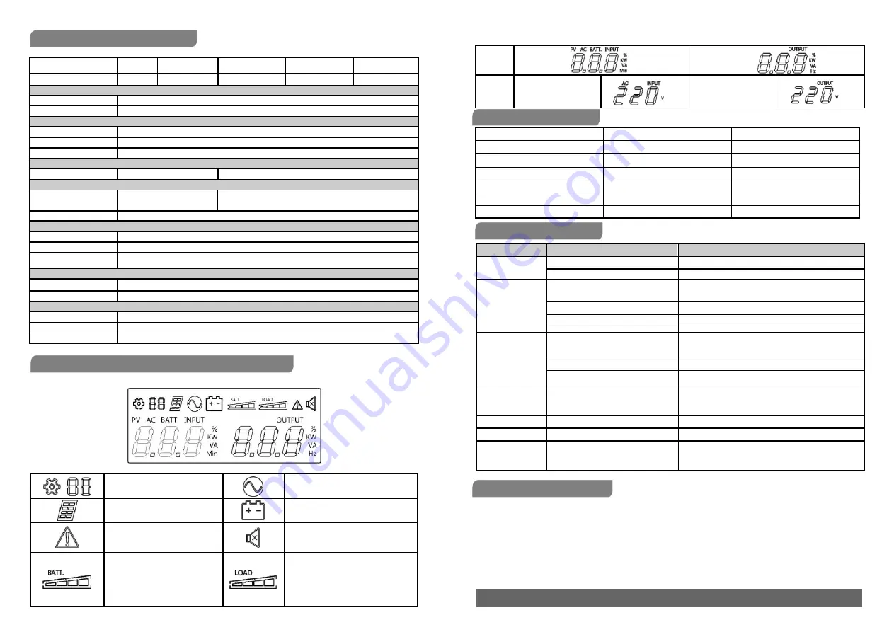
TECHNICAL SPECIFICATIONS
Model
ECO II-801
ECO II-1k LED
ECO II-1K LCD
ECO II-1.2k LED
ECO II-1.2K LCD
ECO II-1.5k LED
ECO II-1.5K LCD
ECO II-2.2k LED
ECO II-2.2K LCD
Capacity (VA/W)
800/480
1000/630
1200/720
1500/900
2200/1320
Input
Nominal Voltage
220Vac
Nominal Frequency
50/60Hz
Output
On Battery Output Voltage
Simulated Sine Wave at /-10%
On Battery Output Frequency
50/60Hz +/-1%
Overload Protection
Fuse/Breaker
Physical
Dimensions (W x H x D)(mm)
96 x 138 x 286
148 x 178 x 298
Battery
Sealed Maintenance
12V x1
12V x2
Free Lead Acid Battery
Typical Recharge Time
8 Hours
Warning Diagnostics
Indicators
Power On
Audible Alarms
On Battery, Low Battery, Overload, Fault
Display
LED( For ECO II-801/
ECO II-1k LED/ ECO II-1.2k LED/ ECO II-1.5k LED/ ECO II-2.2k LED)
LCD( For ECO II-1K LCD/ ECO II-1.2 K LCD / ECO II-1.5 K LCD / ECO II-2.2 K LCD)
Environmental
Operating Temperature
0
℃
to 40
℃
Operating Relative Humidity
0 to 90%
Management
Auto-Charger
Yes
Auto-Restart
Yes
USB COMM. Port
Only for LCD models
DEFINITIONS FOR ILLUMINATED LCD INDICATORS
LCD Indication
Setting Item
Line mode
PV mode
Bat-mode
Sound disable
Fault
(Press the display key 3s to disable
and enable the buzzer sound)
Bat mode: battery capacity
Line mode:
1. Battery charging: cycle lighting
Load capacity
2. Battery full charged: lighting
3. Line mode without charger:
battery capacity
Line mode & Batt. Mode
Initial
AC INPUT (Voltage)
V
OUTPUT (Voltage)
V
LED Indication and Alarm
LED Display (only for LED models)
Alarm
Normal
Green LED lighting
Off
Battery Discharge
Yellow LED flash once every 30 seconds
Beep once every 30 seconds
Battery Low
Yellow LED flash once every 2 seconds
Beep once every 2 seconds
Overload
Red LED flash once every 0.5 second
Beep once every 0.5 second
Off mode charging
All LED off
Off
Fault
Red LED lighting
Continuous alarm
Problem
Possible Cause
Solution
The UPS does not
perform expected
runtime
Batteries are not fully charged.
Recharge the battery by leaving the UPS plugged in.
Battery is slightly worn out.
Contact Technical Support.
The UPS will not turn
on.
The on/off switch is designed to prevent
damage by rapidly turning it off and on.
Turn the UPS off. Wait 10 seconds and then turn the
UPS on.
The unit is not connected to an AC outlet.
The unit must be connected to a 220V
ac
50/60Hz outlet.
The battery is worn out.
Contact Technical Support.
Mechanical problem.
Contact Technical Support.
Outlets do not
provide power to
equipment
Circuit breaker is tripped due to overload
Turn the UPS off and unplug at least one piece connected
equipment. Unplug the power cord of the UPS then press
the circuit breaker knob.
Batteries are discharged
Allow the unit to recharge for at least 4 hours.
Unit has been damaged by a surge or
spike
Contact Technical Support.
Fault code F09
Output Short :
Output circuit short.
Shut down the UPS
Your attached equipment may have problems, please remove
them and check again.
Fault code F12
Battery voltage is too low.
Shutdown your computer and recharge the battery immediately.
Fault code F13
Battery is overcharged.
Contact Technical Support.
Fault code F14
Overload occurs:
Your equipment requires more power than
the UPS can provide. It will shutdown.
Shut off non-essential equipment.
If this solves the overload problem, the UPS will transfer to
normal operation.
SOFTWARE DOWNLOAD
Power Master management software provides a user-friendly interface for your power systems. The graphic user interface is intuitive and
displays essential power information at a glance. Please follow procedure below to install the software.
Installation procedure:
1. Download Power Master from the website: http://www.powermonitor.software/
2. Double-click the file and follow the installation steps.
When your computer restarts, the Power Master software will appear as a blue icon located in the system tray.
K01-C000349-03
All rights reserved. Reproduction without permission is prohibited
TROUBLE SHOOTING


