


Voyager | 12
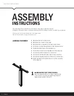
ASSEMBLY INSTRUCTIONS
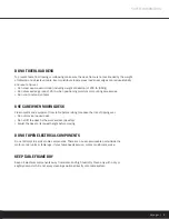
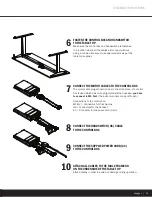
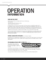
CONNECT THE HANDSWITCH (HS) CABLE
TO THE CONTROL BOX
CONNECT THE SUPPLIED POWER CORD (AC)
TO THE CONTROL BOX
CONNECT THE MOTOR CABLES TO THE CONTROL BOX
The motor cable plug-connection has to click into place. If a control
box is used which has more plug-terminals than needed,
you have
to connect to M1 first.
(The extra terminals can be left open.)
Connections to the control box:
M1-M2 = Connectors for the columns
HS = Connectors for the handset
AC = Connector for the power cord (3-pin)
ATTACH ALL CABLES TO THE TABLE FRAME OR
ON THE UNDERSIDE OF THE TABLE TOP
Attach cables in order to avoid any damage during operation.
FASTEN THE CONTROL BOX AND HANDSWITCH
TO THE TABLE TOP
Make sure the control box and handswitch are fastened
in a location where all the cables will connect without
being in tension. Be sure to use approved screws per the
table top supplier.
6
8
9
7
10