098-00028-000 Revision F – May, 2012
TimeProvider 5000 User’s Guide
87
Chapter 2 Installing
Making Ground and Power Connections
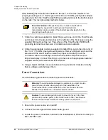
4. Using 1 mm² / 18 AWG (minimum) stranded wire, connect primary power to the
connectors per the polarity markings. Use the polarity markings of "-48V" and
"RTN" as a reference for the proper polarity connection..
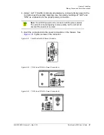
5. Insert the connectors into the power connections in the chassis. See
. Tighten screws in the connector
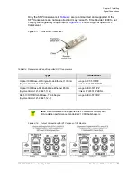
Figure 2-31. TimeProvider 5000 Power Connector
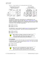
Figure 2-32. TP E10 and TP E30 - Power Connector A
Figure 2-33. TP E10 and TP E30 - Power Connector B
Note:
The -48VDC power must be connected with the proper polarity.
The unit will not be damaged by reverse polarity, but the unit will not
operate if the polarity is reversed.
Содержание TimeProvider 5000
Страница 12: ...Table of Contents 12 TimeProvider 5000 User s Guide 098 00028 000 Revision F May 2012 ...
Страница 16: ...List of Figures 16 TimeProvider 5000 User s Guide 098 00028 000 Revision F May 2012 ...
Страница 20: ...List of Tables 20 TimeProvider 5000 User s Guide 098 00028 000 Revision F May 2012 ...
Страница 56: ...56 TimeProvider 5000 User s Guide 098 00028 000 Revision F May 2012 Chapter 1 Overview Alarms ...
Страница 270: ...270 TimeProvider 5000 User s Guide 098 00028 000 Revision F May 2012 Chapter 3 Simple Network Management Protocol SNMP ...
Страница 370: ...370 TimeProvider 5000 User s Guide 098 00028 000 Revision F May 2012 Chapter 5 Operating Managing PTP Clients ...
Страница 524: ...524 TimeProvider 5000 User s Guide 098 00028 000 Revision F May 2012 Appendix F PTP Probe Option Analyzing Probe Data ...
Страница 534: ...Index W W 534 TimeProvider 5000 User s Guide 098 00028 000 Revision F May 2012 ...

