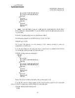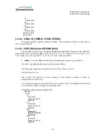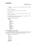
DOC06501_Revision
F
ATS-6501 Users Guide
18
2.4 Antenna Delay Calibration
Utilizing the ATS-6501 as a precise time recovery system requires a complete calibration
of the ATS-6501 and distribution system. Cables and distribution equipment external to the ATS-
6501 affect the calibration of the overall system and will result in an offset from UTC(USNO).
This section assumes the on-time-point (OTP) of the system is the rear panel outputs on the ATS-
6501. This may not be the desired location for the OTP; users should refer to section 2.5 for
information on changing the location of the OTP for the system.
For applications requiring the highest level of accuracy, the ATS-6501 should be
calibrated at Symmetricom. This process involves installing the user’s antenna and antenna cable
at the factory and comparing the PPS outputs to a system which has a known offset to
UTC(USNO). Once the calibration is complete, the antenna delay value is provided to the
customer when the unit is delivered to the user. The PPS outputs will be accurate to the precise
calibration levels specified in Appendix A as long as the user installs the antenna at a surveyed
location. If a surveyed antenna location is not available, the ATS-6501 can be used to survey the
location. See Section 2.3.5 on determining the antenna position.
A coarse calibration of the ATS-6501 is accomplished by accounting for the individual
system delays and combining them to determine the overall delay of the system. This method is
generally less accurate because the individual delays in the system are estimated and may not be
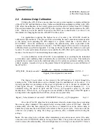
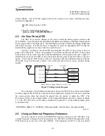
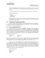
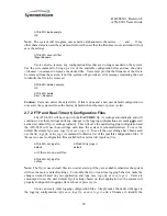
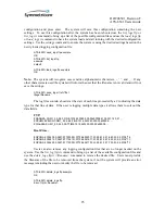
entirely accurate. Equation 2-2 gives the general formula for performing a coarse calibration of
the ATS-6501.
9
5
.
48
)
sec
/
(
_
)
(
_
_
_
)
(sec
_
ATS_6501
E
ond
meters
Velocity
Signal
meters
Cable
Antenna
of
Length
onds
Delay
Eq. 2-2
The
Signal_Velocity
refers to the velocity of the GPS signal as it travels through the
antenna cable. This information can be obtained from the manufacturer of the cable. It is
typically specified as a percentage of the speed of light and it is up to the user to calculate the
actual
Signal_Velocity
. Calculation of the
Signal_Velocity
is shown in Equation 2-3. It is
calculated using the speed of light and the
Velocity_of_Propagation
given by the cable
manufacturer. If the
Velocity_of_Propagation
is not available or the accuracy of the PPS signal is
not important to the application then 0.85 may be used as a typical value.
pagation
_Pro
of
Velocity
ond
meters
Velocity
Signal
_
*
299792458
)
sec
/
(
_
Eq. 2-3
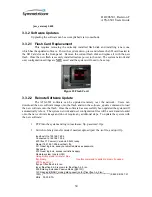
Once the ATS-6501 delay has been calculated, it must be entered into the system using
the
antenna_delay
command. The example below is using a delay value of 118.5nsec. Once the
antenna delay value has been properly set use the
save
command to save the current delay to
ensure the system uses the correct delay value after a reboot or power cycle. Users can verify the
value was set properly by using the
settings gps:antenna_delay
command and reviewing the
settings.
Note:
The new delay value will take effect immediately and could cause an alarm if the delay
value forces the UTC(UNSO) offset to be larger than 100ns. The system will steer the internal
clock to remove the antenna delay, if the alarm light came on it will go out once the UTC Value is
Содержание ATS-6501 Tflex
Страница 6: ......
Страница 106: ...DOC06501_Revision F ATS 6501 Users Guide 100 Appendix F Certificate of Compliance ...


