

1-12-1
D6N_SC
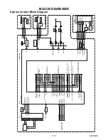
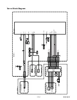
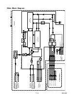
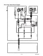
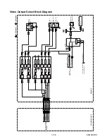
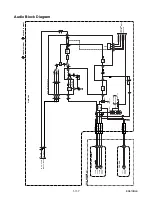
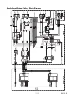
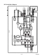
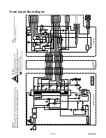
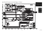
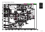
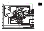
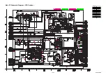
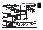
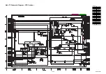
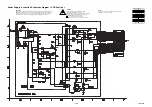
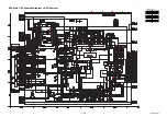
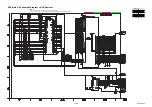
SCHEMATIC DIAGRAMS / CBA’S AND TEST POINTS
Standard Notes
WARNING
Many electrical and mechanical parts in this chassis
have special characteristics. These characteristics
often pass unnoticed and the protection afforded by
them cannot necessarily be obtained by using
replacement components rated for higher voltage,
wattage, etc. Replacement parts that have these
special safety characteristics are identified in this
manual and its supplements; electrical components
having such features are identified by the mark “
#
” in
the schematic diagram and the parts list. Before
replacing any of these components, read the parts list
in this manual carefully. The use of substitute
replacement parts that do not have the same safety
characteristics as specified in the parts list may create
shock, fire, or other hazards.
Notes:
1. Do not use the part number shown on these
drawings for ordering. The correct part number is
shown in the parts list, and may be slightly
different or amended since these drawings were
prepared.
2. All resistance values are indicated in ohms
(K = 10
3
, M = 10
6
).
3. Resistor wattages are 1/4W or 1/6W unless
otherwise specified.
4. All capacitance values are indicated in
µ
F
(P = 10
-6
µ
F).
5. All voltages are DC voltages unless otherwise
specified.
Содержание DVR90VF
Страница 18: ...1 6 5 E9601DC Fig D9 19 Deck Pedestal 20 Front Bracket R S 19 S 19 S 20...
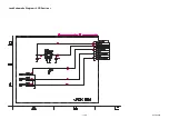
Страница 48: ...1 12 11 Jack Schematic Diagram VCR Section E9610SCJK...
Страница 78: ...1 18 2 E9610PEX Packing S1 A14 S2 S2 S2 Unit S3 Some Ref Numbers are not in sequence X1 X22 X4 X20 X5 X2 X3 S2...
Страница 88: ...DVR90VF E9610UD 2005 04 01...