


1-6-2
E9601DC
Reference Notes
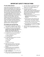
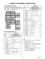
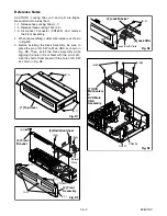
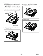
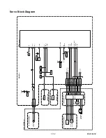
CAUTION 1: Locking Tabs (L-1) and (L-2) are fragile.
Be careful not to break them.
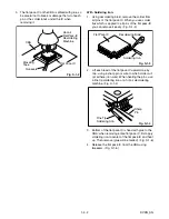
1-1. Release five Locking Tabs (L-1).
1-2. Release three Locking Tabs (L-2)
1-3. Disconnect Connector (CN1609), and remove
the Front Assembly.
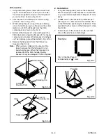
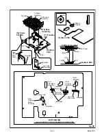
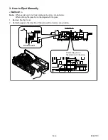
2. When reassembling, solder wire jumpers as shown
in Fig. D8.
3. Before installing the Deck Assembly, be sure to
place the pin of LD-SW on Main CBA as shown in
Fig. D8. Then, install the Deck Assembly while
aligning the hole of Cam Gear with the pin of LD-
SW, the shaft of Cam Gear with the hole of LD-SW
as shown in Fig. D8.
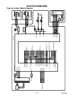
(S-1)
(S-1)
(S-1)
[1] Top Cover
Fig. D1
(L-1)
(S-2)
(S-2)
(S-3)
Shield
Plate
(L-2)
(L-1)
(L-1)
[2] Front
Assembly
[3] Front
Bracket
[4] Radiation Sheet
CN1609
Fig. D2
Fig. D3
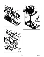
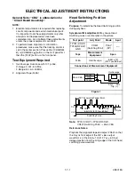
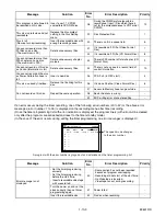
(S-4)
Jack Earth Plate
[5] Jack Bracket
[6] Jack CBA
Fig. D4
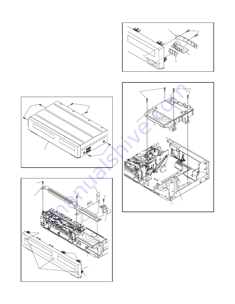
(S-5B)
(S-5A)
CN2204
CN201
[7] DVD
Mechanism
&
DVD Main
CBA
Assembly
Содержание DVR90VF
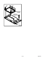
Страница 18: ...1 6 5 E9601DC Fig D9 19 Deck Pedestal 20 Front Bracket R S 19 S 19 S 20...
Страница 48: ...1 12 11 Jack Schematic Diagram VCR Section E9610SCJK...
Страница 78: ...1 18 2 E9610PEX Packing S1 A14 S2 S2 S2 Unit S3 Some Ref Numbers are not in sequence X1 X22 X4 X20 X5 X2 X3 S2...
Страница 88: ...DVR90VF E9610UD 2005 04 01...


