2-3-1
L0655TSG
TROUBLE SHOOTING GUIDE
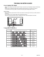
How to identify SOS Signal
When an abnormality has occurred in the PDP module, the protection circuit operates and reset to the stand-by
mode.
Below are how to identify SOS signal. We can specify the portion which is out of order by this method.
It is conditions that main power CBA, sub power CBA, analog CBA and digital CBA are normal.
[How to check]
Remove CLN10(from Digital CBA to D CBA Unit), connect an oscilloscope to the No. 3 pin of D8 connector on
D CBA Unit.
Then connect AC cord, a power supply will be automatically turned on.
If power is shut down by protection circuit, a waveform as shown in the following figure is observed.
Timing Chart of Waveform
SC
SS
D
CLN10
Remove
D2 connector
D8 connector
Contents & Check point
SOS Signal timing (at the No. 3 pin of D8 connector)
Number of Pulse
2
3
5
6
7
8
9
15V SOS
(D CBA Unit)
3.3V SOS
(D CBA Unit)
5V SOS
(D CBA Unit)
Driver SOS1
(SC CBA Unit)
Driver SOS2
(SC, SU,
SD CBA Unit)
Driver SOS3
(SS CBA Unit)
Config SOS
(D CBA Unit)
Содержание 6842PF M
Страница 33: ...6842PF M L0654UE 2006 09 14...


