background image

20060913

1-5-1

L0654CA

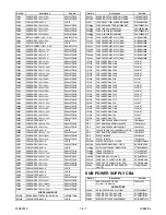
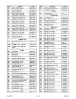
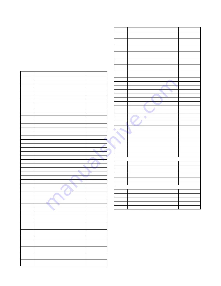
MECHANICAL PARTS LIST

PRODUCT SAFETY NOTE:

 Products marked with a 

#

 have special characteristics important to safety. 

Before replacing any of these components, read 
carefully the product safety notice in this service 
manual. Don't degrade the safety of the product 
through improper servicing.

NOTE:

 Parts that are not assigned part numbers 

(---------) are not available.

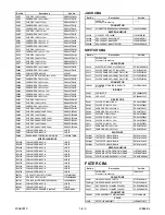
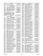
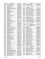
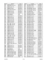
Ref. No.

Description

Part No.

A1

STAND COVER L0600UA

0EM000953

A2

STAND L0600UA

0EM201832

A3

STAND BASE L0600UA

0EM201865

A4

RUBBER FOOT L0600UA

0EM408992

A5

JACK COVER L0652UC

1EM020487

A6

#

JACK LABEL(R) L0652UC

----------

A7

#

JACK LABEL(L) L0652UC

----------

A8

#

RATING LABEL L0654UE

----------

A9

FRONT CABINET L0652UC

1EM020490A

A10

DECORATION PANEL L0600UA

1EM020390

A11

SENSOR/LED LENS L0600UA

0EM408988

A12

BRAND BADGE L0600UA

0EM409093

A13

REAR CABINET L0700UA

0EM000907A

A14

REAR COVER L0600UA

0EM408989

A15

#

AC CORD LABEL L0600UA

----------

A16

JACK HOLDER L0600UA

0EM201861

A28

SW PCB HOLDER L0650UA

1EM120488

A29

CONTROL PLATE L0600UA

0EM302072

AC4601

#

AC CORD PH8F3EDGN0A-063

WBC0192LW001

B3

EARTH LABEL L0600UA

----------

B4

PANEL HOLDER(U) L0650UA

1EM020408

B5

PANEL HOLDER(L) L0650UA

1EM020407

B6

FILTER HOLDER(L) L0650UA

1EM020467

B7

FILTER HOLDER(S) L0650UA

1EM120669

B8

PANEL HOLDER(S) L0650UA

1EM120490

B10

SPEAKER HOLDER L0650UA

1EM220421

B11

SPEAKER COVER L0600UA

1EM220002

B12

PCB BOX L0650UA

1EM020249

B14

CHASSIS BRACKET L0700UA

1EM020895

B16

JACK BRACKET L0650UA

1EM120489A

B17

GASKET-B L0600UA

0EM409061

B18

GASKET(L) L0650UA

1EM421664

B25

CUSHION(L) L0650UA

1EM421666A

B26

CUSHION(S) L0650UA

1EM421667A

B28

CLOTH L1440JL 15X55XT1.0

0EM406793

B29

PCB POST L0650UA

1EM421819

B32

SCOTCH TAPE #880 25X45 L9710UL

0EZZ00132

CLN1

WIRE ASSEMBLY 17C(LVDS) 17 260 AWG28 
RED WHI

WX1L0650-019

CLN2

WIRE ASSEMBLY 8P(DIGITAL PCB POWER 
WX1L0650-002

WX1L0650-002

CLN3

WIRE ASSEMBLY 9P(SW PCB) WX1L0650-004 WX1L0650-004

CLN4

WIRE ASSEMBLY 10P(JACK PCB) WX1L0650-
005

WX1L0650-005

CLN5

WIRE ASSEMBLY 2P(R CH SPEAKER) 
WX1L0650-006

WX1L0650-006

CLN6

WIRE ASSEMBLY 2P(L CH SPEAKER) 
WX1L0650-007

WX1L0650-007

CLN8

WIRE ASSEMBLY 11P(ANALOG PCB POWER 
WX1L0650-010

WX1L0650-010

CLN9

WIRE ASSEMBLY 4P(AUDIO POWER) 
WX1L0650-011

WX1L0650-011

CLN10

WIRE ASSEMBLY 10C(MAINPSU-ANALOG) 10 
390 AWG28 RED GRA

WX1L0650-020

CLN11

WIRE ASSEMBLY 13C(MAINPSU-LOGIC) 13 
240 AWG28 YELLOW

WX1L0650-021

CLN12

WIRE ASSEMBLY 3C(MAINPSU-SCAN) 3 200 
AWG24 YELLOW G

WX1L0650-022

CLN13

WIRE ASSEMBLY 7C(MAINPSU-SUSTAIN) 6 
700 AWG24 YELLOW G

WX1L0650-023

CLN14

WIRE ASSEMBLY 3C(MAINPSU-SCAN) 2 200 
AWG18 YELLOW G

WX1L0650-024

CLN15

WIRE ASSEMBLY 3C(MAINPSU-SUSTAIN) 2 
700 AWG18 YELLOW G

WX1L0650-025

CLN16

WIRE ASSEMBLY 1P(SW GND) WX1L0650-018 WX1L0650-018

CLN603

WIRE ASSEMBLY 1P WX1L0600-018

WX1L0600-018

FC1

FERRITE CORE RFC-8

XL06034WD002

FL501

OPTICAL FILTER PS08FZ001

XA00000SM006

JK4601

#

AC INLET FILTER 10GEEG3C

JTDCFZ0DEL01

L1

SCREW P-TIGHT 3X10 BIND HEAD+

GBJP3100

L4

SCREW B-TIGHT D3X8 BIND HEAD+

GBJB3080

L5

DOUBLE SEMS SCREW M4X8 PAN HEAD+

0EM409074A

L7

BINDING HEAD SCREW M3X8

SBJ33080

L8

DOUBLE SEMS SCREW M3X8 PAN HEAD+

0EM409075A

L9

SCREW ASSEMBLED M3X6 BLACK

0EM409078A

L10

DOUBLE SEMS SCREW M5X16 PAN HEAD+

0EM409236A

L11

SCREW P-TIGHT D4X12 BIND HEAD+

GBJP4120

L12

DOUBLE SEMS SCREW M5X20 PAN HEAD+

0EM409077A

L14

DOUBLE SEMS SCREW M4X12 PAN HEAD+

1EM420188A

L15

SCREW M3X8 BIND HEAD+BLACK

SBH33080

L16

SCREW B-TIGHT M3X8 BIND HEAD+

GBHB3080

PDM501

PLASMA DISPLAY MODULE MD-42S9NJB

UDPUPLSMS002

SP801

SPEAKER MAGNETIC S0407F14

DSD0807XQ005

SP802

SPEAKER MAGNETIC S0407F14

DSD0807XQ005

PACKING

S1

STYROFOAM TOP L0652UC

1EM322231

S2

STYROFOAM BOTTOM L0652UC

1EM322238

S3

SET BAG (L) L0600UA

0EM302075A

S4

CARTON(U) L0652UC

1EM320880

S5

CARTON(L) L0652UC

1EM320860

S6

#

SERIAL NO. LABEL L0654UE

----------

ACCESSORIES

X1

#

OWNERS MANUAL ENGLISH/SPANISH

1EMN20890B

X2

BAG POLYETHYLENE 235X365XT0.03

0EM408420A

X4

DRY BATTERY(SUNRISE) R6SSE/2S

XB0M451MS002

X3

REMOTE CONTROL NE801UD

NE801UD

X5

#

EASY SET UP GUIDE L0652UC

1EMN20891

Ref. No.

Description

Part No.

Содержание 6842PF M

Страница 1: ...inted to the model number Refer to the Rating Label on the back of the unit to make sure model types This service manual is for the 6842PF M A version model and shows only the differences between the...

Страница 2: ...A DISPLAY 6842PF M TABLE OF CONTENTS Electrical Adjustment Instructions 1 1 1 Block Diagrams 1 2 1 Schematic Diagrams CBA s and Test Points 1 3 1 Waveforms 1 4 1 Mechanical Parts List 1 5 1 Electrical...

Страница 3: ...A Fig 1 2 How to set up the service mode Service mode 1 To turn the power on press POWER button on the normal remote control unit or the unit 2 Use the service remote control unit 3 Press SLEEP button...

Страница 4: ...perate the unit more than 20 minutes 2 Input the gray scale pattern signal 5 scales from Composite AV Input 1 video jack Video1 3 Set the color analyzer to the CHROMA mode and after zero point calibra...

Страница 5: ...s shown below 10 Press 1 button on the normal remote control unit for Red adjustment Press 3 button on the normal remote control unit for Blue adjustment 11 In each color mode press CH o p button to a...

Страница 6: ...Q2301 15V REG SB ON2 PS SOS PANEL ON 31 SUS MONITOR 32 ADR MONITOR 2 3 6 6 4 2 4 5 14 15 8 9 11 12 SWITCHING CONTROL WF12 J2144 HOT GND J2198 VADD J2064 DC15V J2156 CFM J2176 GND WF14 WF16 WF13 WF15 D...

Страница 7: ...rawings for ordering The correct part number is shown in the parts list and may be slightly different or amended since these drawings were prepared 2 All resistance values are indicated in ohms K 103...

Страница 8: ...since the drawings were prepared 2 To maintain original function and reliability of repaired units use only original replacement parts which are listed with their part numbers in the parts list sectio...

Страница 9: ...wer supply circuit are not defective before you connect the AC plug to the AC power supply Otherwise it may cause some components in the power supply circuit to fail For continued protection against r...

Страница 10: ...pply circuit are not defective before you connect the AC plug to the AC power supply Otherwise it may cause some components in the power supply circuit to fail For continued protection against risk of...

Страница 11: ...e it may cause some components in the power supply circuit to fail For continued protection against risk of fire replace only with same type 2A 250V fuse CAUTION ATTENTION Utiliser un fusible de recha...

Страница 12: ...upply Otherwise it may cause some components in the power supply circuit to fail For continued protection against risk of fire replace only with same type 2A 250V fuse CAUTION ATTENTION Utiliser un fu...

Страница 13: ...Shown in Schematic Diagram WF2 WF3 1DIV 1V 10ms Z3731 WF9 1DIV 500mV 20 s C3103 WF6 1DIV 500mV 20ns UPPER TP3197 TP3198 WF4 LOWER WF8 WF7 UPPER Pin 2 of IC4801 Pin 4 of IC4801 LOWER WF11 WF10 1DIV 10...

Страница 14: ...ACK PCB WX1L0650 005 WX1L0650 005 CLN5 WIRE ASSEMBLY 2P R CH SPEAKER WX1L0650 006 WX1L0650 006 CLN6 WIRE ASSEMBLY 2P L CH SPEAKER WX1L0650 007 WX1L0650 007 CLN8 WIRE ASSEMBLY 11P ANALOG PCB POWER WX1L...

Страница 15: ...0V M CA1J4R7SP085 C4716 ELECTROLYTIC CAP 47 F 16V M CA1C470SP085 C4717 CHIP CERAMIC CAP F Z 0 01 F 50V CHD1JZ30F103 C4718 CHIP CERAMIC CAP 1608 CH J 33pF 50V CHD1JJ3CH330 C4719 CERAMIC CAP AX B K 1000...

Страница 16: ...03 R4309 CHIP RES 1 10W J 100 RRXAJR5Z0101 Ref No Description Part No R4310 CHIP RES 1 10W J 10k RRXAJR5Z0103 R4311 CHIP RES 1 10W J 10k RRXAJR5Z0103 R4312 CHIP RES 1 10W J 10k RRXAJR5Z0103 R4315 CARB...

Страница 17: ...UMPER D0 6 P5 0 JW5 0T BC4708 PCB JUMPER D0 6 P5 0 JW5 0T JK4701 Y C JACK 1P SW YKF51 5586N JYEL040JC003 JK4702 RCA JACK YKC21 4616N JYRL030JC008 JK4703 RCA JACK WHITE RED YKC21 4042N JXRL020JC024 JS4...

Страница 18: ...iption Part No C2308 CERAMIC CAP AX F Z 0 01 F 25V CCA1EZTFZ103 C2350 FILM CAP P 0 1 F 50V J CA1J104MS029 C2352 CAP ELE SML 105 10 F 25V M CE1EMASTJ100 C2353 ELECTROLYTIC CAP 470 F 100V M CE2AMZNTJ471...

Страница 19: ...NG DIODE 1SS133 T 77 QDTZ001SS133 D2463 ZENER DIODE MTZJT 776 8B QDTB0MTZJ6R8 Ref No Description Part No D2500 LED GREEN LTL 1CHGE NPQZLTL1CHGE D2515 SWITCHING DIODE 1SS133 T 77 QDTZ001SS133 ICS IC210...

Страница 20: ...0223 R2251 PCB JUMPER D0 6 P20 0 JW20 0T Ref No Description Part No R2252 METAL OXIDE FILM RES 3W J 47k RN03473ZU001 R2253 CARBON RES 1 4W J 820 RCX4JATZ0821 R2254 CARBON RES 1 4W J 4 7k RCX4JATZ0472...

Страница 21: ...Z0332 MISCELLANEOUS BC2200 BEADS INDUCTOR FBR07HA121SB 00 LLBF00STU030 BC2300 PCB JUMPER D0 6 P5 0 JW5 0T Ref No Description Part No BC2301 BEADS INDUCTOR FBR07HA121SB 00 LLBF00STU030 BC2400 BEADS IND...

Страница 22: ...D2071 ZENER DIODE MTZJT 776 8B QDTB0MTZJ6R8 D2072 ZENER DIODE MTZJT 776 8B QDTB0MTZJ6R8 ICS IC2000 PHOTO COUPLER LTV817MCF NPECLTV817MF Ref No Description Part No IC2001 PHOTO COUPLER LTV817MCF NPECLT...

Страница 23: ...00 LLBF00STU030 BC2002 BEADS INDUCTOR FBR07HA121SB 00 LLBF00STU030 BC2050 BEADS INDUCTOR FBR07HA121SB 00 LLBF00STU030 BC2051 BEADS INDUCTOR FBR07HA121SB 00 LLBF00STU030 F2000 FUSE 4A 250V PB FREE 021...

Страница 24: ...ASMA DISPLAY MODULE SECTION PLASMA DISPLAY 6842PF M TABLE OF CONTENTS Safety Precautions 2 1 1 CBA Structure Parts List 2 2 1 Trouble Shooting Guide 2 3 1 Adjustment Procedure 2 4 1 Wiring Diagram 2 5...

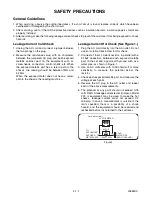
Страница 25: ...chassis the reading must be Leakage Current Hot Check See Figure 1 1 Plug the AC cord directly into the AC outlet Do not use an isolation transformer for this check 2 Connect a 1 5k 10 watts resistor...

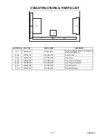
Страница 26: ...Processor Sub Field Processor 2 SS 1ESA13794 SS CBA UNIT Sustain Drive 3 SC 1ESA13792 SC CBA UNIT Scan Drive 4 SU 1ESA13795 SU CBA UNIT Scan Drive Out Upper 5 SD 1ESA13793 SD CBA UNIT Scan Drive Out...

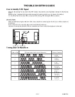
Страница 27: ...om Digital CBA to D CBA Unit connect an oscilloscope to the No 3 pin of D8 connector on D CBA Unit Then connect AC cord a power supply will be automatically turned on If power is shut down by protecti...

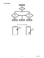
Страница 28: ...2 3 2 L0655TSG NO PICTURE NO Picture Check OSD Check LED D6583 Check LED D6253 OK OK SC CBA Unit D CBA Unit SS CBA Unit NG NG Drive circuits LED indicator SC CBA Unit LED D6583 LED D6253 SS CBA Unit...

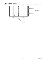
Страница 29: ...display may have local area failure on the screen Figure 2 is the possible defect CBA for each local area SU CBA Unit SD CBA Unit D CBA Unit C2 CBA Unit D CBA Unit C1 CBA Unit D CBA Unit Figure2 SS CB...

Страница 30: ...ver section voltages as shown below Name Test Point Voltage Volume Remarks Ve TPVE SS Ve 1V VR6000 SS See the Panel label Vset TPVSET SC 232V 7V Fixed Vad TPVAD SC 90V 1V VR6600 SC Vscn TPVSCN SC Vad...

Страница 31: ...t Point Voltage Volume Remarks SC CBA Unit Vad TPVAD SC 90V 1V VR6600 SC SS CBA Unit Ve TPVE SS Ve 1V VR6000 SS See the Panel label D CBA Unit Adjustment is not required SU CBA Unit Adjustment is not...

Страница 32: ...PLASMA DISPLAY PANEL SD1 TO PLASMA DISPLAY PANEL TO PLASMA DISPLAY PANEL SD2 SD3 SS42 SS41 SS43 SS44 D20 D5 CB1 CB2 CB3 TO PLASMA DISPLAY PANEL CB4 CB5 CB6 CB7 D31 C11 D32 C21 SS23 C23 SC2 SC23 C22 SC...

Страница 33: ...6842PF M L0654UE 2006 09 14...

Отзывы: