


7
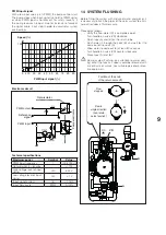
INSTALLATION
Alarm display
If the pump detects one or more alarm conditions, LED 1
changes from green to red. When an alarm is active, the
LEDs indicate the type of alarm as shown in the following
table. If more than one alarm is active at the same time, the
LEDs only show the alarm condition with the highest priori-
ty. Alarm priority follows the order of the table.
When no alarm is active, the user interface automatically
displays pump performance.
Nr. dis-
played
Meaning
Function
Action
LED 1 red
and LED 5
yellow, both
lit
The pump
rotor is
blocked
The pump
automatically
attempts to
start every
1.5 seconds
Wait or
check that
the pump
rotor is free
to rotate
LED 1 red
and LED 4
yellow, both
lit
Supply volt-
age too low
Indica-
tion only.
The pump
continues to
function
Check the
voltage of
the power
supply
LED 1 red
and LED 3
yellow, both
lit
Electronic
controller
error
The pump
has stopped
because
supply
voltage is
too low or
because an
error has
occurred in
the internal
electronic
controller
Check the
voltage of
the power
supply or
replace the
pump
SETTING MODE
Setting display
To switch from performance display to setting display,
press button (1). The LEDs shows the current setting. See
the following table for the meaning of the LED display.
Setting display mode shows the type of pump control or
the currently selected pump curve. Settings cannot be
changed in performance display mode. After 2 seconds,
the display returns to performance display mode.
Led n.1: if red it reveals an alarm or an external control;
if green it indicates the circulator performance or internal
control possibility.
Led n. 2 and 3 indicate different control mode possibility
and led n. 4 and 5 indicate the curve type setting (1,2,3 o
4). These leds are yellow.
PWM mode
LED
1
LED
2
LED
3
LED
4
LED
5
Curve 1 (4,5m)
Red
-
Yel-
low
-
-
Curve 2 (5,5m)
Red
-
Yel-
low
Yel-
low
-
Curve 3 (6,5m)
Red
-
Yel-
low
Yel-
low
Yel-
low
Curve 4 (7,5m) (*)
Red
-
Yel-
low
-
Yel-
low
(*)
Default setting
Direct speed control mode.
LED
1
LED
2
LED
3
LED
4
LED
5
Curve 1 (4,5m)
Green Yel-
low
Yel-
low
-
-
Curve 2 (5,5m)
Green Yel-
low
Yel-
low
Yel-
low
-
Curve 3 (6,5m)
Green Yel-
low
Yel-
low
Yel-
low
Yel-
low
Curve 4 (7,5m) (*)
Green Yel-
low
Yel-
low
-
Yel-
low
(*)
Default setting
Button lock/unlock function
The button lock function serves to prevent improper use or
accidental changes to pump settings.
When the button lock is active, pressing the button has no
effect. This prevents users from accidentally accessing set-
ting mode while allowing them to use setting display mode.
To enable/disable the blocking function, press (1) key for
more than 10 seconds. In doing this, all the leds will flash,
except for the red one, to indicate the switching of the
blocking function.
Setting mode
To modify settings, press the button (1) for between 2 and
10 seconds. Users can only select new settings provided
the button lock function is disabled.
Available settings are displayed in a pre-defined sequence
that is repeated every time the button is briefly pressed and
released.
If the button is not pressed for over 10 seconds, the pump
exits setting mode and returns to performance display
mode.
See the table above for the meanings of the LED sequenc-
es.
> 10 s.
SETTING MENU
PERFORMANCE
> 2 s.
X
10 s.
2 s.
SELECTED SETTING


