background image


V1.1 

sy.uk 

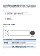
Front Panel Operation 

To use the front panel controls the LOOP output switch must be set to OFF. When the 
LOOP output is ON, then the MUSIC level is fixed to 100%, the MIC input is muted and 
the front panel controls are locked out. 

Input Selection 

The INPUT SEL button selects between the analogue Line In connector and the digital 
Optical input. 

Mic Mute 

Press to mute or unmute the Mic input. The current mute status is shown on the display. 

Line Mute 

Press to mute or unmute the Line input. The current mute status is shown on the display. 

Volume Control 

The volume control is used to change the volume for either the Line input or the Mic input 
separately as well as muting or unmuting both the Mic and Line inputs at the same time. 


To change the Line input level, the MIC input must be muted. 


To change the Mic input level, the MIC input must not be muted. 


When both Mic and Line are unmuted, then only Mic level control is operational. 


Press  the  volume  knob  to  mute  /  unmute  the  output.  Rotating  volume  knob 
automatically unmutes the output. 

Note:

 The mute state previously set by the input mute buttons is not altered 

when pressing the volume control. 

Display Panel 

The display panel provides the following information: 


The selected audio input: 

LIN

 or 

OPT


The mute status of the Mic and Line inputs. The mute state is indicated by the 
word 

MUT

 on the respective input display line. 


The volume level of the Mic and Line inputs, each shown as a percentage  of 
the full output volume level, or 

MUT

 when set to 0% level. 

Special Messages on the Display 

PROTECT


This message will appear when the amplifier has detected a problem and had to shut 
down to protect itself from damage. When this happens do the following: 

1. 

Switch off the amplifier. 

2. 

Check that ALL the switch settings on the rear panel are correct. 

3. 

Check that the input signal levels are within specification. 

4. 

Check that output speaker wiring and loads are correct and to specification. 

5. 

Only turn on the amplifier when all the above checks have been confirmed as 
correct. 

Содержание 2A-100W

Страница 1: ...SY Electronics Ltd 7 Worrall Street Salford Manchester M5 4TH Tel 44 0 161 868 3450 Web sy uk User Manual 2A 100W Dual input 100W Stereo Amplifier LAN RS232 IR control ...

Страница 2: ... 100W output power in stereo mono or bridge configurations Analogue Stereo or Optical Toslink audio inputs Microphone input with 48V phantom power mic level or line level modes Loop out option that can feed to another SY 2A 100W OLED front panel display LAN control RS232 control IR control 24V DC PSU Panel Descriptions Front Panel Item Description INPUT SEL Select either Line LIN or Optical OPT In...

Страница 3: ...ical fibre input LOOP OUT Output the amplifier signal to connect to another amplifier LOOP MODE Selects whether the loop mode is on or off SPEAKERS Speaker outputs Connect in accordance with the MODE switch System Connection Connection Procedure Set the switches on the rear of the amplifier to the correct positons according to the installation requirements Connect the audio source to the relevant ...

Страница 4: ...en the display shows PROTECT immediately switch off the amplifier and rectify the condition that caused the amplifier to enter its protection mode before switching it back on MIC Switch This switch provides three modes of operation 1 48V for phantom powered condenser microphones 2 MIC for dynamic or self powered electret microphones 3 LINE for any line level audio signal or pre amplified radio mic...

Страница 5: ... Details Figure 6 Unbalanced Line Level Wiring Details Speaker Mode Switch The speaker mode switch should be set to match speaker wiring before the amplifier is switched on The SY 2A 100W has three speaker configurations 1 STEREO Use two 50W 4R speakers one each across the L L and R R for the left and right speakers Each speaker will output their respective stereo signal ...

Страница 6: ...this mode the first amplifier should have its LOOP switch OFF and all the other amplifiers should have the LOOP switch set to ON Only the first amplifier will have control of the output volume level and also allows a microphone to be used Note The following conditions apply when using the LOOP OUT switch LOOP OUT Setting OFF ON Operating Mode NORMAL LOCKED Front Panel Control All controls will fun...

Страница 7: ... level control is operational Press the volume knob to mute unmute the output Rotating volume knob automatically unmutes the output Note The mute state previously set by the input mute buttons is not altered when pressing the volume control Display Panel The display panel provides the following information The selected audio input LIN or OPT The mute status of the Mic and Line inputs The mute stat...

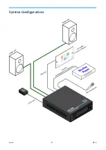
Страница 8: ...sy uk 8 V1 1 System Configuration ...

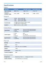
Страница 9: ...s max 15Hz 20kHz Connections Signal Inputs 1 x MIC LINE 1x LINE 1x OPTICAL 3 way screw terminal connector 3 way screw terminal connector TosLink S PDIF Control Inputs 1x LAN 1x IR 1x RS 232 RJ45 3 5 mm jack 3 way screw terminal connector Signal Outputs 1x LOOP 1x SPEAKER 3 way screw terminal connector 4 way screw terminal connector Physical Housing Aluminium Colour Black Dimensions 193 x 145 x 44 ...

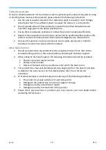
Страница 10: ...w any liquids or harmful chemicals to come into contact with this product After Sales Service 1 Should you experience any problems while using this product firstly refer to the Troubleshooting section in this manual before contacting SY Technical Support 2 When calling SY Technical Support the following information should be provided Product name and model number Product serial number Details of t...

Страница 11: ...V1 1 11 sy uk NOTES ...

Страница 12: ...sy uk 12 V1 1 NOTES ...

Отзывы: